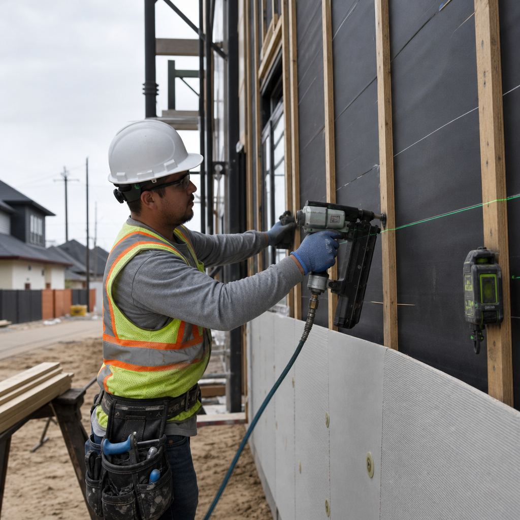
Rainscreen wall assemblies in Houston, TX must strike a precise and code-driven balance between water management, hurricane-resistant attachment, careful barrier transitions, and permit approval efficiency. Every detail-cavity gap, WRB layering, anchor schedule, flashing overlap, and plan-set note-undergoes scrutiny for compliance with the FBC/IBC as amended in Houston’s Construction Code. Plans that succeed in navigating this landscape chart their way through meticulous annotations, explicit dimensions, and proven approaches to resolving common redlines in Houston’s ePermits system. Each phase, from first-section cut to last ePermit upload, is governed by technical specifics: 2021 IBC/IRC with local amendments, ASCE 7 load calculations, and explicit Zoning District overlays.
Detailing FBC/IBC-Compliant Rainscreen Cavity Geometry, Drainage, and Weep Provisions in Houston
Cavity Geometry: Ensuring a Capillary Break That Meets Houston’s Adopted Code
IRC Section R703.1 requires exterior walls-whether within residential or multifamily typologies-to “provide the building with a weather-resistant exterior wall envelope.” Every rainscreen wall detail must illustrate a well-defined cavity gap, forming a capillary break between cladding and water-resistive barrier (WRB). As per industry best practice, the minimum drainage gap in this climate is 1/8 inch (3 mm), although high-exposure assemblies often specify a 3/4 inch continuous air space using proprietary batten or mesh products.
- Plan notation: “Install continuous 3/4" rainscreen batten system (e.g., Benjamin Obdyke Slicker Classic or equal) between WRB and cladding. Min. air gap: 3/4". Refer Detail 3/A7-2.”
- Common redline: “Rainscreen cavity depth not specified. Detail required” or “Capillary break noncompliant with IRC R703.1.”
Ventilation of Rain Cavity: Both top and bottom of the rainscreen gap need to be ventilated and protected. Plan sheets for Houston frequently call out “vented closure strip with 1/8" slot openings at base and eave; all vent openings to be insect-screened with 1/16" mesh SS screen.” Dimensioned sections must show vent field at minimum 16 in² per lineal foot for soffit or base ventilation where required by manufacturer/system.
Drainage Planes and Overlaps: WRB Layering and Flashing
IRC Section R703.2 and IBC Section 1402.2 dictate a water-resistive barrier applied “in shingle fashion” over studs or sheathing, “free of breaks and holes.” Houston’s adopted amendments and permitters consistently redline any break in the WRB path or missing overlap in wall details. Best practice for overlapping WRBs and flashings, per IRC 2024 and code commentary:
- Horizontal WRB overlap: minimum 2 inches (51 mm).
- Vertical WRB lap at seams: minimum 6 inches (152 mm).
- Flashing under cladding: all horizontal flashings “integrated with WRB above, lapped minimum 4" by WRB, extending to daylight or face of cladding.”
Details and notes must show shingle-fashion layering at ALL transitions: window heads, sills, base-of-wall, and parapet/roof interfaces. Redline comments in Houston frequently cite “Unclear WRB lap at horizontal joint-must lap over flashing” or “Missing dimension at WRB seam. Minimum 2" required (IRC R703.2).”
Weep Provisions at Base and Fenestrations: Drawn, Called Out, and Inspected
- Base of wall: Weep screeds, per IRC R703.6.2.1, must be provided at the base of wood or metal framed walls with stucco or similar adhered veneer. Drawings must note “Install 0.019" (No. 26 ga.) galvanized weep screed, 3.5” vertical flange, min. 4" above earth/2" above paving.” The WRB must lap over this flange, directing drainage outward-callouts and section cuts at grade are expected.
- Window and door openings: All fenestrations require head, jamb, and sill flashing, each integrated shingle-style with the WRB. IRC Section R703.4: “Flashing shall be installed at... exterior window and door openings,” and must be explicit in drawings. Plan review comments in Houston typically require: “Detail integration of pan/metal flashing at windows-continuous with WRB. Show end dams and minimum 1” upturn.”
Window head and sill details should read: “24-gauge galvanized steel head flashing, min. 6" past jambs with 1" end dams, WRB lapped above 4" minimum. Sill pan with 4" backleg, side dams 1”, fully adhered membrane (AAMA 711).”
Houston-Specific Code Amendments and Common Plan-Review Notes
Houston’s adopted amendments (2021 IBC/IRC) reinforce high-performance requirements and routinely trigger plan corrections when rainscreen assemblies are drawn generically. Drawings must:
- List Houston Construction Code and amendments on cover and in General Notes.
- Annotate WRB, rainscreen gap, drainage plane, and weep at each wall and transition detail.
- Dimension every WRB overlap, flashing lap, gap, and vent field.
- Detail line-item material spec per section cuts; redlines regularly state “Specify WRB and flashing by mfr/type, not generic.”
Selections for WRB, flashing, and cavity system must include ASTM and AAMA compliance in the notes: “Install self-adhered WRB, ASTM E2556 Type II, vapor-permeable, 40-mil thickness,” or “All flashing to AAMA 711, 26 ga. galvanized steel.”
Engineering Rainscreen Attachments for Hurricane Wind Loads: Drawings and Review in Houston
Wind Load Calculation and Code Citations
Houston is within ASCE 7-16 wind-borne debris and high-velocity hurricane zones, requiring every exterior cladding detail and schedule to call out compliance with IBC 2021 Chapter 16, Section 1609: “Components and cladding shall be anchored to resist wind loads in accordance with ASCE 7-16.” Local amendments must be annotated: “All cladding attachment and CI fasteners per Houston IBC Amendments, Sec. 1609, ASCE 7-16 exposure C. Design wind speed per TDI map: Vult = 130-140 mph.”
Cladding and Furring Fastener Schedules
- Attachment tables: Every wall section and exterior cladding note must call out a fastening schedule. Redlines for “Unclear fastener size/spacing at furring strips” are common.
- Typical plan annotation: “Furring strips: 2x2 PT wood, secured to structure at 16” o.c. vertically, 3/8"x5" hex-head lag screws, embed 1.5" min. into framing. Furring attachment per engineering calculations, see Table S2.1.”
- Cladding (fiber cement): “Panels fastened through furring with 2-1/4" SS ring-shank siding nails at 12" o.c. vertically. All fasteners corrosion-resistant, per ICC-ES AC233.”
Schedules should be placed on dedicated sheet (e.g., S3.2 Cladding and CI Attachment Schedule) and referenced at all section details. For continuous insulation systems, the insulation manufacturer’s ICC-ES or FM approval must be cited-plan reviewers regularly mark “CI attachment unspecified-provide system and fastening spacing for design load.”
CI Securement: Houston Redlines and Field Practice
Continuous insulation (CI) must be drawn with fastening patterns that account for the compressive strength of the foam, the wind pressure, and thermal movement. A typical notation: “R-5 Extruded Polystyrene CI, 1-1/2" thick, dual washer fasteners, 12" o.c. vertically at each stud, length to penetrate min. 1-1/2" into framing, provide shop drawings for review.” Fastener patterns must be shown at wall plan, elevation, and section-redlines often include “Show CI fastening pattern at all elevations exposed to >150 mph wind.”
- CI performance: Must meet ASTM C578 (XPS) or C1289 (polyiso), closed-cell, compressive strength 20 psi minimum.
- Typical specification callout: “CI insulation: 1.5" XPS, ASTM C578 Type IV, continuous, fasten per attachment schedule S3.2 and wind pressure calcs.”
Sections and details must demonstrate that cladding anchors pass through furring/CI and are embedded into structural framing with code-minimum edge distances and embedment. Houston’s most common plan comment on high-wind rainscreen assemblies: “Detail furring strip and cladding attachment through continuous insulation-show fastener type, spacing, and penetration. Note ASCE 7 wind pressure and exposure.”
Wind Design and Fastener Submittals: Drawing-Sheet Conventions
- Wind load summary table must be present on the structural notes page and cross-referenced at each relevant detail.
- Attachment and CI fastener patterns should be shown “typ” at mid-wall, corners, and openings. Provide enlarged corner/edge details if pattern changes near edges.
- Detail references to manufacturer anchor test reports (ICC-ES), and clearly state “All fastener capacities per tested values and submitted submittal package.”
Seamless Air and Vapor Barrier Integration with the Rain Cavity: Wall Section Protocol in Houston’s Climate Zone 2A
AVB Material, Performance, and Code in Houston
Houston’s hot-humid climate (IECC Climate Zone 2A) and adopted 2021 IBC, Section 1404.3.1, define strict boundaries for (and against) AVB product selection and layering. For spray-foam hybrids, code text: “Spray foam plastic insulation with max. permeance 1.5 perms, interior side, is deemed to satisfy the continuous insulation moisture control requirement if installed thickness achieves or exceeds R-value of CI prescribed.”
Material standard note: "Air Barrier: Fluid-applied vapor-permeable membrane, < 0.04 cfm/ft² (ASTM E2178), vapor transmission >10 perms (ASTM E96 Proc. B), thickness per mfr., color: blue."
Foundation, Roof, and Slab Edge AVB Transitions
- Foundation-wall interface (Section Detail 4/A5.1): “Fluid-applied AVB to be applied over slab edge and up exterior sheathing, lapped min. 12" vertical. Terminate behind WRB, base flashing lapped over AVB. Stainless drip-edge flashing, 1" projection beyond exterior finish. Seal all AVB/WRB laps with mastic per mfr.”
- Roof-wall junction (Detail 7/A8.2): “AVB membrane turned up wall and integrated below main roof membrane with 6" vertical lap. Use butyl transition membrane per ABAA detail. Head flashing metal extends 6" minimum, terminated over AVB layer. Provide crimped hem to maintain AVB continuity and water deflection.”
- Slab edge (Section 4/A5.1, again): “R-5 rigid insulation at slab edge, AVB membrane sealed (polyether liquid or equal) to top of insulation. All transitions compatible, installed per mfr. details.”
Every wall section must include enlarged insets at these transitions, with explicit layers, callouts, and dimensioned interfaces. Common redline in Houston plan review: “AVB continuity at slab and wall/roof not clear-provide detail. Indicate sealant and flashing transition.”
Drawing-Sheet and Call-Out Standards
- Section references: “Foundation AVB transition-see Detail 4/A5.1” “Roof-to-wall AVB transition-see Detail 7/A8.2.”
- Material callouts: “Air/vapor barrier, fluid-applied, color coded blue for inspection. Vapor permeable, 40 mil wet, < 0.04 cfm/ft², ASTM E2178.”
- Flashing/AVB lap: “Lap all membranes min. 6" shingle fashion. All laps and terminations to be trowel-sealed.”
- All AVB transitions must be dimensioned to show overlap (6"-12"), thickness, and termination, with notes describing compatibility (“All AVB/flashing transitions must be approved by membrane manufacturer and compatible per submitted submittals”).
- Redline resolution: Drawings must highlight the direction of water and air flow with arrows-common Houston comment: “Clarify water & air path. Show continuity through wall assembly.”
Complex Rainscreen Junctions: Flashing and Penetration Detailing per IBC/IRC and Houston Amendment
Head, Jamb, and Sill Integration-Drawn for Plan Review and Field Durability
IRC Section R703.4 and IBC Section 1404.4 are explicit: “Approved corrosion-resistant flashing shall be applied over all exterior window and door openings” and at “all wall penetrations and terminations.” Houston redlines regularly cite generic “noted” flashing as noncompliant-plan sheets must show:
- Head flashing: “24 ga. galvanized head flashing, 6" past jambs, 1" end dams, wrb lapped min. 4" above, flashing at 10° slope.”
- Jamb flashing: “Self-adhered butyl membrane, AAMA 711, 4" face, lapped 4" over WRB, shingle-style at interface, return at inside jamb.”
- Sill/pan flashing: “Thermoformed sill pan or liquid-applied membrane, 4" upturned at back, 1" end dams, slope to exterior. Extend membrane 6" up jamb both sides.”
Details must be supported by material schedule call-outs, e.g.: “Head flashing: 26 ga. galv. steel, 0.019" min., 6" past window, 1” end dams; Jamb flashing: AAMA 711 butyl, 30 mil; Sill pan: thermoformed, 1" upturn, AAMA 711 compliant.”
Through-Wall Penetration Detailing (HVAC, Electrical, Plumbing)
All penetrations demand explicit flashing and sealing details. IRC R703.4: “Flashing shall be applied ... at all penetrations to prevent water intrusion.” Houston’s amendments (see ASPE Houston) reinforce this point. Typical draft detail language:
- Pipe penetration: “Provide annular ring, caulk with one-part polyurethane sealant (ASTM C920), min. 3/8" thickness, embed penetration in tape seal (AAMA 711), lap WRB 4" over flashing. Detail 2/A9.4.”
- Electrical box: “Self-adhered membrane patch (AAMA 711) 4" each side of penetration, caulk perimeter, fasteners set in sealant before install.”
- HVAC sleeve penetration: “Galvanized sleeve, WRB tightly lapped and taped above, closure ring interior/exterior, sealant (ASTM C920), code-compliant firestop if required.”
WRB and Flashing Overlaps, Terminations, and Redline Resolution
- Horizontal WRB laps: Minimum 2", verticals 6".
- End dams at head and sill flashing: 1" minimum to prevent edge bypasses.
- Sealant callouts: “Joint sealant: elastomeric, ASTM C920, Tool all exterior beads to ensure positive seal. Color: match substrate. See schedule S4.3.1.”
Typical Houston permit comment for insufficient detail: “Window flashing lacks end dam and WRB integration; revise detail to show shingle lap and end dam.” Resolution: Provide explicit section detail showing all overlaps drawn, every membrane labeled, and end dams dimensioned. Sheet notes reference material specs (“6" jamb overlap, per submittal, not field judgment”).
Navigating Houston’s ePermits Plan Review-Plan-Set Order, Sheet Protocols, and Zoning District Callouts for Rainscreens
Plan-Set Organization and Drawing Practices for Houston Permitting
Houston permit reviewers expect:
- Cover sheet with adopted code/version: “All work to comply with 2021 IBC/IRC as amended by City of Houston Construction Code (eff. 1/1/2024).”
- General Notes page: List of all code sections specifically invoked (IBC 1403, 1404, IRC R703) and referenced Houston amendments.
- Site plan sheets: Full legal lot description, zoning overlay listed-e.g., “Zoned: R-1 Single Family District” or “Urban Corridor 1/Transit Corridor Overlay.”
- Wall section sheets (A5.1, A7.2, etc.): “Enlarged typical wall section-rainscreen cavity, WRB, CI/AVB, cladding attachment, head/jamb/sill details cross-referenced. All dimensions, materials, and overlaps fully annotated.”
- Schedules and tables: Fastening/attachment schedule (see S3.2), insulation R-value table (see EN1.1), window/door schedule with manufacturer/model/spec. Cross-reference every detail by callout and sheet number.
Every sheet must:
- Include a title block with project, client, date, and revision info (common Houston comment: “Add date and index on all sheets-submittal cannot be processed without date”);
- Use consistent callout conventions: “Detail X/A7-2” for every reference to a drawing, with EN1.1, S3.2, etc., for tables.
- List all Houston-specific notes relevant to wall assembly: “Install all assemblies per manufacturer and Houston amendment. Rainscreen assemblies to be inspected prior to cladding. CI product ICC-ES listed. Fastening per structural calculation.”
- Clearly annotate: “3/4" rainscreen gap,” “WRB overlap: 2" horizontal, 6" vertical,” “Fastening: see S3.2,” “Cladding: 5/16" fiber cement panel,” “CI: 1.5" XPS, Type IV.”
ePermits Review Workflow and Redline Management
- Typical submittal/response cycle: Upload sheets in ePermits per log sheet, ensure plan-set index matches attachment list (PDF naming protocol is enforced-“A5.1_WALL_SECTION.pdf” not “wall sec.pdf”).
- Redlines from Houston plan reviewers often include:
- “Provide rainscreen cavity dimension and fastening schedule at each exterior wall assembly (ref. IBC 1403/IRC R703).”
- “Flashings at windows and doors must include end dams and WRB integration; provide full detail.”
- “Continuous air/vapor barrier must be shown at all transitions; enlarge typical section.”
- “CI attachment to structure noncompliant-fasten schedule and ICC-ES submittal required.”
- Redline resolution: Always address each comment by sheet and detail reference. If submitting a revised detail, highlight changed areas and cloud/revise markups per Houston protocol. Quote code section in revision note (“Revised Detail 3/A7-2 to show 3/4" rainscreen gap and updated WRB lap per IRC R703.2”).
Zoning District Impacts on Wall Assemblies and Sheet Notation
Certain Houston zoning overlays (e.g., Urban Corridors, Historic Districts) impose additional requirements for materials, wall articulation, and setback transitions. Drawings must:
- Note zoning district on site and elevation sheets-e.g., “Urban Corridor 1” overlays may require explicit variance or cladding type restriction.
- Reference “Approved cladding list, per zoning district” in material schedules if applicable.
- Additional storm drainage and permeable area calculations on site plans are frequently required for neighborhood districts.
Plan comment protocol: “Indicate wall assembly compliance with R-1 setback transition” or “Historic District: show cladding/color per COA requirements.” Sheet organization and index must keep this zoning data accessible for all reviewers.
Conclusion
FBC/IBC-compliant rainscreen wall assemblies in Houston are a symphony of detail-each cavity gap, overlapping barrier, anchor, and transition memo must be explicitly annotated, material-scheduled, and dimensioned. Houston’s adopted code and local amendments require not only best-practice water management and high-wind anchorage, but also exacting plan-sheet conventions, precise scheduling, and redline responsiveness within every digital submittal. Projects that master plan organization, code note referencing, and technical clarity in wall sections set the standard for durable, resilient, permit-ready envelopes from the bayou to the edge of the urban corridor.
For accuracy, speed, and code-aware communication, Kingsway Drafting & Design delivers plan sets that pass Houston’s scrutiny the first time.