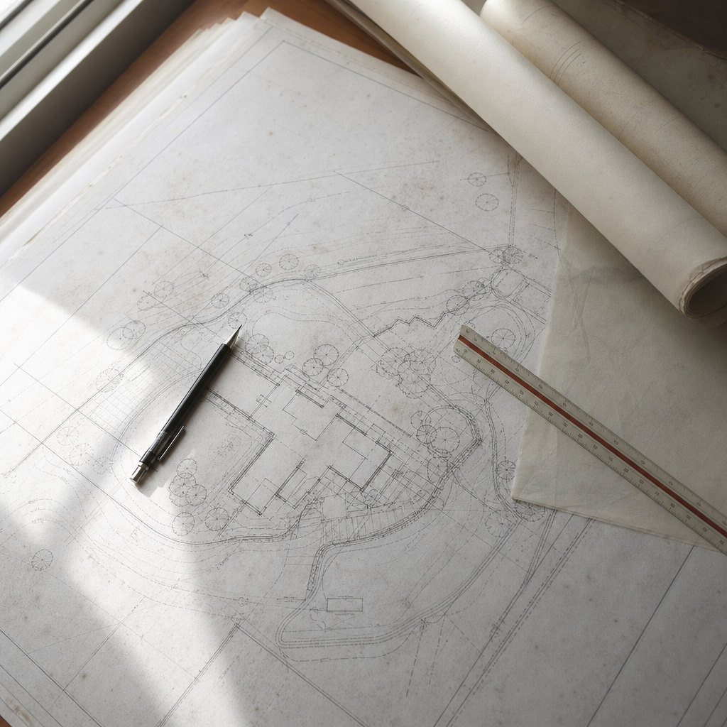
The sloping of finished grade away from Dallas residential foundations is a strict requirement under the 2021 International Residential Code, Section R401.3, and is routinely enforced with detail and precision by the Dallas Building Inspection Division. Site grading, drainage conveyance, impervious cover calculations, and erosion control must be fully detailed on construction documents to comply with the Dallas Development Code and City Code local amendments, as well as to survive plan review and pre-construction redlines. A coordinated approach-involving precise dimensioning, specific material call-outs, and code citations on every relevant sheet-is necessary for permit and construction success.
Site Grading and Positive Drainage Plans: Sheet Conventions, Code Citations, and Plan Review Realities
Surface Drainage Slopes and IRC R401.3
Every Dallas residential project must document how surface water will be directed away from foundations. Section R401.3 of the 2021 IRC, adopted by Dallas effective May 12, 2023 (IRC 2021), sets the baseline: "Surface drainage shall be diverted to a storm sewer conveyance or other approved point of collection so as to not create a hazard. Lots shall be graded to drain surface water away from foundation walls. The grade shall fall a minimum of 6 inches (152 mm) within the first 10 feet (3048 mm) measured perpendicular to the face of the wall..." For hardscaped surfaces within that 10-foot zone, a minimum 2% slope is required per the same section.
Dallas routinely cites this code on redlines: "Site grading plan must demonstrate 6" fall in first 10'. Revise contours to comply with IRC R401.3 and Dallas City amendments."
Dallas Local Amendments, Geotechnical Submittals, and Setbacks
Local ordinances expand upon the IRC, requiring engineered soils and geotechnical documentation for many sites. Dallas City Code Section 51A-5.207 specifies submittals for areas of geological concern:
- Grading plan-including existing/proposed contours, spot elevations at foundation corners and swales, and all drainage and erosion control features
- Soil engineering report per Dallas City Code §51A-5.207
- Engineering geology report, if required by jurisdictional map or upon plan reviewer request
Setback lines must be clearly shown according to the zoning district, for example, the R-7.5(A), R-5(A), or R-1(A) Single Family districts set minimum front setbacks of 25 feet, minimum side setbacks of 5 feet, and rear setbacks of 5 feet (dallas.gov). Plans are often redlined for mislocated structures or grading encroaching into setback areas with notes like: "Revise contours and drainage swale outfalls to remain clear of required rear yard setback per §51A-4.112."
Drawing Details: Conventions and Required Information
The typical Dallas grading and drainage sheet includes:
- Title block with project information and sheet number (e.g., "C1.1 - Site Grading and Drainage Plan")
- Legend identifying proposed vs. existing contours (usually 1-foot intervals), impervious surfaces, swales, and drainage infrastructure symbols
- North arrow, scale bar (no less than 1"=20' for most urban lots; show scale both graphically and as text)
- Labeled spot elevations at building corners, high/low points, and swale inverts
- Call-out examples:
- "6" FALL IN 10' AWAY FROM FDN (IRC R401.3)"
- "2% SLOPE MIN. AWAY FROM GARAGE APRON TO STREET"
- "DRAINAGE SWALE SLOPE: 1% MIN., 4% MAX. SEE DETAIL 2/C1.2"
- Arrows indicating surface water flow direction
- Zoning setback lines as dashed lines labeled "R-7.5(A) SIDE SETBACK, TYP."
Dimensions and Specs to Include
All drawings must quantify:
- 6" fall over 10' (5% slope) minimum on pervious areas adjacent to foundations
- 2% minimum slope for impervious surfaces within 10' of a structure
- Swale longitudinal slope 1%-4% (per City of Dallas Drainage Manual §4.500)
- Typical swale cross-section call-out: "MIN. 2' BOTTOM WIDTH, MAX 4:1 SIDE SLOPES"
Material call-outs should reference ASTM standards for geomembranes if shown (e.g., “HDPE liner per ASTM D1248”), and all erosion control features (e.g., “soil-stabilization blanket per manufacturer's specs”). Construction notes must reference required engineering reports absent from the plans; omissions trigger rejections: "Soils report not included with grading plan per §51A-5.207. Submit signed PE report prior to further review."
Residential Stormwater Conveyance Systems: Pipes, Swales, and Area Drains in Dallas Drawings
Code and Manual References for Stormwater Conveyance
All stormwater systems are governed by the City of Dallas Drainage Design Manual and Dallas City Code Section 51A-8.611 ("Storm Drainage Design"), which requires systems “adequate for the acceptance, collection, conveyance, detention, and discharge of stormwater runoff.” Private systems must be fully maintained by the homeowner, whereas public storm sewer responsibility is retained by the city. Residential site plans frequently include a mixture of surface swales, below-grade pipes, and surface inlets, each with unique drafting requirements.
Swales and Bioswales: Criteria and Drafting
- Longitudinal slope for vegetated swales: 1% minimum to 4% maximum (Drainage Design Manual §4.529)
- Drop structures or check dams required for slopes above 2% to reduce erosion
- Bioswale sections: Min. 2-foot bottom width, 4:1 side slopes (3:1 if geotechnically feasible), and 6-12" max. ponding depth
- Call-out on site plan: "4:1 MAX SIDE SLOPES, 2' MIN BOTTOM WIDTH; SLOPE 1%-4% (SEE PROFILE A/A SHEET C2.2)"
Pipes, Area Drains, and Trench Details
- Trunk lines: Minimum 18" diameter reinforced concrete pipe (RCP), Manning’s n value 0.012, or corrugated metal pipe (CMP) with n=0.024
- Area drains and inlets: Sized for the local 100-year design storm requirement; typically 12"-24" box inlet, with debris-resistant grates and access for cleaning
- Profiles: All storm lines require invert elevations, length, slope, and specification call-outs (“6" PVC SDR-35 STORM SEWER @ 1% MIN. SLOPE, TYP.”)
- Outfall and discharge points: Shown on the overall site plan, ending in approved discharge area, with notes e.g.,"Discharge to City R.O.W. per Section 51A-8.611(e)"
Details Sheet and Plan-Review Redlines
Plan-reviewers routinely request both plan views and section views showing:
- Flow arrows, contours, and invert elevations for all conveyance systems
- Material call-outs ("Area Drain: 12" x 12" HDPE, NDS, see Detail 5/C3.1")
- Discharge location compliance and maintenance access easements for all private systems. Redline example: "Provide dedicated access easement for rear yard storm drain as required by City of Dallas Drainage Manual §2.320."
Drawings must also cite design storm event basis: "All stormwater features sized for 1% annual chance event per City of Dallas Drainage Manual."
Calculating and Representing Impervious Cover on Dallas Site Plans: Protocols for Zoning Compliance
Lot Coverage and Impervious Surface Limits by Zoning District
Dallas Development Code (DDC Art. IV) sets specific maximum lot coverage and impervious coverage ratios by zoning district. For example, R-7.5(A) allows a maximum of 45% lot coverage by building footprint-exclusive of surface parking and at-grade patios unless otherwise stipulated. Although lot coverage is distinct from impervious cover, the city is moving towards tighter impervious surface rules (see 2024 code amendment initiative at dallascityhall.com).
The plan reviewer’s most frequent impervious area redline: "Provide table showing total lot area, total impervious surface area (roofs + paved walks/drives), and resulting percentage. Revise to confirm compliance with [district] cap per §51A-4.112(c)(2)."
Drawing Sheet Strategies: Legends, Tables, and Annotations
- Pervious vs Impervious Legend: Use clear, distinct hatching for driveways, walks, patios, buildings. Example: "Solid hatch: concrete/pavers (impervious), Diagonal hatch: landscaping (pervious)"
- Lot Coverage Table: Always include an area table:
- Total lot area (SF)
- House footprint (SF)
- Paved walkways/driveways/patios (SF)
- Total impervious area (sum)
- Lot coverage % = (impervious area/lot area) x 100
- Dimension and Tagging: Linear dimensions of all impervious elements, dimension ticks marking extents, and direct area call-outs ("452 SF CONCRETE DRIVEWAY-IMPERVIOUS, SEE TABLE")
- Compliance notes: "Impervious coverage does not exceed 45% per DDC §51A-4.112."
Material and Specification Call-Outs
- Concrete driveways: 4" thick, 3000 psi min, with contraction joints at 10' max o.c.
- Asphalt: 2" HMAC over 6" compacted base
- Pavers: Interlocking, on 4" crushed stone base with sand joints
Include manufacturer detail references for specialty surfaces, and note any pervious paver systems in contrast to solid-surface concrete/asphalt. Plans omitting this differentiation risk redlines for ambiguous impervious calculations.
Temporary Erosion and Sediment Control Details: Silt Fence, Construction Entrance, and Inlet Protection
Code and Local Ordinance Requirements
Temporary erosion measures are fully integrated into Dallas permit review under City Code §51A-5.206 and §19-118.6, which mandate a soil erosion control plan and enforcement of Best Management Practices (BMPs) for sediment control (§51A-5.206, §19-118.6). The required erosion plan must:
- Show all temporary control devices-silt fences, stabilized construction entrances, and inlet protections-with labeled installation locations and detail cross-references
- Be certified by a registered Professional Engineer for geologically sensitive sites
- Explain anticipated schedule for grading operations and BMP installation/removal
- Include maintenance notes, e.g. "Inspect silt fence after rainfall; repair or replace as needed. Remove upon establishment of vegetative cover."
TESC Drawing Conventions and Call-Out Examples
-
Silt Fence:
- "Install silt fence along all downslope limits of disturbance per Detail 2/C4.1"
- Sectional detail: 24" min. above ground, 6" trench, backfilled and compacted, max. 10' post spacing, “Non-woven geotextile, 100 lb. min. tensile”
-
Stabilized Construction Entrance:
- "Stabilized construction entrance: 20' min width x 50' min length, 3-5" clean rock over geotextile fabric per Detail 3/C4.1"
- Profile shows 6" depth, filter fabric, side berms to contain run-off
-
Inlet Protection:
- "Install gravel bag inlet filter per Detail 4/C4.2 at all on-site drain inlets"
- Details show full inlet coverage, maintenance access, overflow provision, minimum rock bag weight for Dallas rainfall rates
Material and Specification Requirements for TESC Devices
- Silt Fence: Non-woven geotextile to ASTM D6461, 100 lb. minimum tensile, steel/wood posts 1.5" diam., 12" embedment
- Construction Entrance: Crushed rock, 3-5" size, min 6" depth over Class 2 filter fabric
- Inlet Protection: Woven/gravel bags designed for 25-year rain event, completely covering inlet with anti-flotation anchors as specified by City of Dallas BMP Manual
Failure to include full TESC details is a near-universal cause for redlines: "TESC plan missing or incomplete. Show silt fencing, stabilized entrances, and inlet protection with referenced details per City Code §19-118.6."
Navigating Dallas Stormwater Plan Review: Redlines, Sheet Standards, and Code Citations for Approval
Typical Permit-Review Comments and Plan Redlines
The Dallas Development Services Department (DSD) and Building Inspection Division have formalized expectations for stormwater management sheets:
- "Batch stamp space missing. Revise all sheets to include 4"x4" approval stamp area as per standard."
- "File must be landscape orientation (not portrait) and named in accordance with City ePlan standards-max 20 characters, no special marks." (See Dallas Best Practices.)
- "Multi-page PDF not accepted. Submit single-sheet PDFs with scale bar, purged of extraneous layers."
- "Cloud all revised areas and include revision narrative with code citations."
Underlying all plan and detail requirements is the necessity for explicit code citations. Sheet call-outs must reference not only the generic code, but also specific Dallas amendments and manual sections (e.g., "Slope per IRC R401.3/Dallas amendment" or "Swale per City of Dallas Drainage Manual §4.521").
Drawing Revisions: Best Practices per Dallas Guidelines
- Cloud and key all revised elements; provide Revision Schedule on each affected sheet
- Accompany resubmittals with full narrative responses ("Plan Reviewer Comment 7: Provided additional silt fence detail on C4.1 as requested. TESC plan now references §19-118.6")
- Include or update all required notes, dimensions, and code citations upon each revision; corrections that reference only generalities ("changed as noted") are routinely rejected
Failure to thoroughly coordinate all elements-grading, drainage, impervious coverage, TESC, utility conflicts, section views-results in extended plan-review cycles and repeated redlines.
Dimensioning and Specification Protocols for Plan Approval
- All slopes, invert elevations, and storm line sizes must be numerically dimensioned and not just diagrammatic
- Drainage detention and containment devices for stormwater must be detailed, including dimensions, overflow, and material specs
- Impervious surface calculations must be explicit, with each area/dimension tagged in both plan and table
- All revisions must retain legacy/milestone stamps and indicate the current cycle and date for city tracking
- Water and wastewater lines must show appropriate separation from storm lines (see Dallas Water Utilities Standards)
Continuous plan coordination, meticulous code referencing, and pre-submittal quality assurance are essential not only for initial approval but also for post-permit compliance and inspections.
Conclusion
Drafting stormwater management plans for Dallas residential permits demands an exhaustive, detail-centric approach on every plan sheet: documenting surface and subgrade drainage away from foundations per IRC R401.3 and Dallas amendments, dimensioning all slopes and stormwater systems per the City of Dallas Drainage Design Manual, representing impervious cover with accurate area tabulations and explicit zoning compliance, specifying all temporary sediment controls with prescriptive city-approved details, and referencing each applicable code section directly on the drawing. Navigating the Dallas plan-review workflow requires single-page, properly oriented PDFs with clouded revisions, current code citations, and fully coordinated drawing sets that address both city redlines and construction realities. Kingsway Drafting & Design delivers this level of rigor on every residential site plan and stormwater management drawing set.