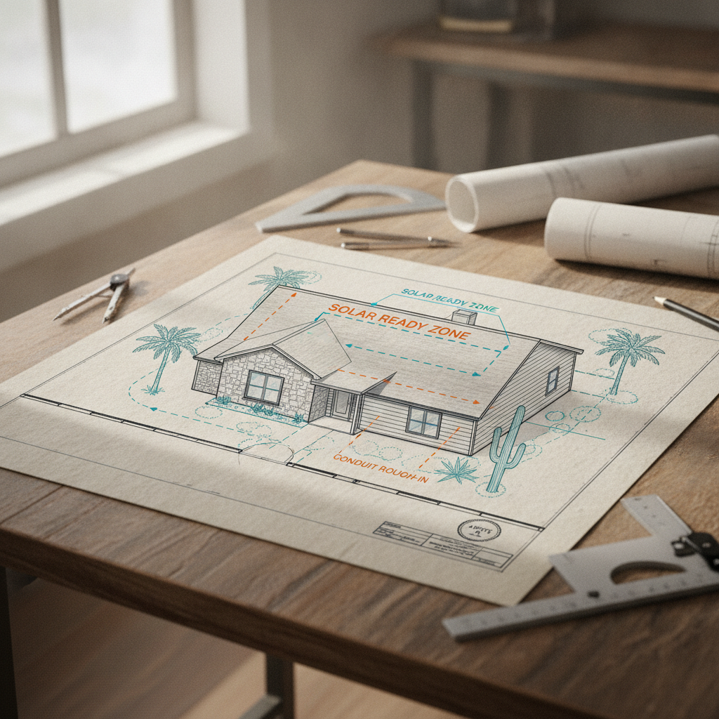
The City of Austin mandates fully detailed solar-ready infrastructure on new residential construction, adopting the 2021 International Residential Code (IRC) along with local amendments and the 2020 National Electrical Code (NEC). For drafters and design teams, getting solar-ready details right means not only meeting technical specification thresholds but also avoiding costly plan-review redlines and field-change orders through holistic, cross-sheet integration.
Detailing the Austin-Specific IRC 2021 Solar Ready Zone on Architectural Roof Plans
Austin’s current code, under IRC 2021 (including Appendix RB-Solar-Ready Provisions for Detached One- and Two-Family Dwellings and Townhouses), requires every new residential dwelling, including single-family (SF-3) lots, to clearly indicate a Solar-Ready Zone on the architectural roof plan. The Austin Energy Code adopts these provisions directly, with nuanced clarifications reflected in project redlines and field inspections.
Minimum Solar-Ready Zone Area, Dimensioning, and Setbacks from Obstructions
The designated Solar-Ready Zone must be explicitly delineated with dashed or bold lines on the roof plan and clearly labeled “Reserved for Future Solar Installation.” For one- and two-family dwellings, the minimum Solar-Ready Zone area is 300 sq. ft., exclusive of access or setback areas. Each individual subzone must be no less than 80 sq. ft. and must have a width of at least 5 ft. For eligible townhouses (≤2000 sq. ft. per unit, three stories or less), the minimum is 150 sq. ft. (IECC 2021 Appendix RB, Section RB103.1.2).
Obstructions such as plumbing vents, mechanical curbs, skylights, and chimneys are prohibited within this zone. Additionally, the Solar-Ready Zone boundary must observe a setback from any object on the south, east, or west that is at least twice the object’s height above the nearest roof point-a direct response to solar access shading impacts (RB103.2.2).
Roof Plan Notations and Drawing Conventions
Standard drafter conventions in Austin employ:
- Solar Ready Zone: Outlined on the roof plan with a heavy dashed line (e.g., ──────) and tagged as “SOLAR READY ZONE - RESERVED FOR FUTURE USE.”
- Dimensions: Linear dimensions are placed parallel to zone edges, with total area calculation called out in a text box adjacent to the zone boundary (e.g., “SOLAR-READY AREA: 325 SQ. FT.”).
- Setback Notation: A leader line to the closest vent or stack, with callout “MINIMUM 2X OBJECT HEIGHT CLEAR FROM ZONE, PER IECC RB103.2.2.”
- Prohibited Items: Any conflicting item within the reserved area shown with a red “X” during design QA/QC reviews-such features must not appear on the permitted set.
General notes are used to cite compliance: “SOLAR-READY ZONE PLANNED PER 2021 IRC APPENDIX RB, ADOPTED AUSTIN AMENDMENTS AND CITY ENERGY CODE SECTION 25-12-32. ZONE IS FREE FROM OBSTRUCTION AND STRUCTURALLY DESIGNED FOR +5 PSF PV DEAD LOAD.”
Common Austin DSD Plan Review Redlines
- “Area of solar ready zone less than 300sf. Revise and resubmit.”
- “Plumbing vent shown within solar ready zone-relocate vent to ensure clear zone.”
- “Setback to east side mechanical curb measures less than 2x curb height-zone boundary must be revised.”
- “Solar ready zone not dimensioned on roof plan-add dimension strings with total zone area calculation.”
Responding to such comments requires the drafter to coordinate with MEP and site layout teams early to finalize obstruction-free rooftop sections before locking plan geometry.
Material and Structural Code Details for the Solar-Ready Zone
The Solar-Ready Zone must also account for increased live and dead loads. Per Appendix RB Section RB106.1, design for an added 5 psf dead load over the zone area to guarantee the roof framing can support future distributed PV modules and racking hardware. Plans must cite the structural assumption-e.g., “STRUCTURAL LOAD CAPACITY ABOVE CODE MINIMUM PROVIDED FOR 5PSF PV DEAD LOAD ACROSS DESIGNATED ZONE.”
Roof material call-outs must specify a product compatible with standard PV mounting systems; for composition asphalt shingles, include notes on fastener compatibility, and for metal roofs, clarify panel type (e.g., “Standing-seam metal roof panels, 24 ga., snap-lock profile, solar mount compatible.”)
Dimensioning and Specifying Dedicated PV Conduit Rough-ins on Electrical Drawings for Austin, TX
PV conduit rough-in requirements are explicitly detailed in the City’s adopted 2020 NEC and Austin Energy’s local amendments, affecting both electrical plan layout and field installation notes. Electrical sheets must provide a clear, code-compliant path for future PV system wiring-from roof deck penetration to the main service panel-with proper sizing, labeling, and routing to minimize destructive retrofits.
Conduit Sizing, Type, and Preferred Routing Paths
Per NEC Article 690 and local practice, the minimum conduit size for future solar is 1 inch diameter, with Schedule 40 PVC accepted for interior runs, and Schedule 80 PVC mandatory for exterior/garage wall vulnerability areas (Texas Electrical Authority).
Electrical plans should trace the pathway as a bold line, indicated on the schematic, called out as:
- (E) 1”Ø SCH. 40 PVC ‘FUTURE PV CONDUIT’ - ROOF, RUN IN ATTIC, DROPPING IN WALL TO APRON J-BOX ADJACENT TO MAIN PANEL."
Junction box locations are identified by symbol (e.g., a square with a cross inside, per ANSI Y32.9), labeled “PV J-BOX-FUTURE USE,” and dimensioned on floor/attic plans for accurate rough-in placement. Where slab or wall frontal access is needed, plans denote “J-BOX TO BE FLUSH WITH WALL, COORDINATE WITH FRAMING.”
Routing through attic and wall cavities must retain full access after insulation and not reduce vapor/air barrier efficacy; seal all penetrations with code-compliant firestop and draftstop products to preserve envelope performance.
Typical DSD Plan Review and Inspection Comments
- “Future PV conduit not continuous-provide a clear route from attic to panel, avoiding structural beams.”
- “Junction box for PV not indicated on plan. Add box and label ‘PV Junction Box for Future Solar Array’.”
- “No reserved location for AC disconnect-show exterior wall space for future NEMA3R-rated disconnect.”
- “Conduit size undersized; revise to 1” minimum, per [2020 NEC Chapter 9 Table 1].”
To comply, reserve two adjacent breaker slots for a future PV backfeed connection inside the main panel, labeled “FUTURE PV - DO NOT USE.” Plan notes should state: “PULL ROPE PROVIDED IN PV CONDUIT. END POINTS CAPPED AND LABELED PER NEC 690.”
Junction Box and Detail Conventions
Junction boxes should meet NEC article 314 enclosure standards and be sized to allow easy access (minimum 4” x 4” x 2-1/8” for up to four conductors). Plan callouts may read: “JUNCTION BOX - 4x4x2-1/8, STEEL, LISTED FOR 600V, LABEL ‘PV ONLY.’” Attach a detail on the electrical sheets, e.g., “Detail 3/E2.1” showing roof penetration, firestopping, and conductor spacing compliance.
Conduit Fill, Bending, and Material Standards
NEC Table 1 (Chapter 9) stipulates that 1” PVC can accommodate up to four #10 AWG conductors at 40% fill for typical residential systems. All bends must meet minimum radii specified in NEC 358.24, and all conduits/fittings used must be UL-listed and compatible with PV circuit voltages (600V rating for typical residential inverters).
Illustrating Structural Load Provisions and Reinforcement Call-outs for Future PV Arrays on Structural Framing Plans in Austin, TX
Every Solar Ready Zone must be mirrored with structural framing beam, rafter, and connection call-outs capable of bearing the additional distributed load imposed by a future PV array. Austin’s adoption of ASCE 7-16 through IRC 2021, as interpreted by DSD, drives explicit notation and reinforcement in the permit set.
Required Notation for Future PV Dead Load Allowances
IRC Appendix RB (RB106) and IBC Section 1607.13.5.2 both set expected future PV panel loads at 5 psf (some engineers recommend 6-7 psf for heavier panels or racking). Framing plans must call out in a general note:
- “DESIGN CRITERIA: ROOF FRAMING AT SOLAR-READY ZONE ENGINEERED FOR +5 PSF DEAD LOAD (PV LOADING) IN ADDITION TO STANDARD ROOF & SNOW LOADS.”
This accounting must be highlighted in structural calculations and visible on the S sheets, ensuring reviewers and contractors see that the roof is fully future-proofed for PV upgrades.
Truss, Rafter, and Deck Reinforcement Details
- Increase rafter size or spacing as required; for example, specify “2x8 SPF No. 2 @ 24” O.C. AT SOLAR-ZONE, BLOCKED SOLID AT SUPPORTS” in the zone area compared to 2x6 elsewhere.
- Add blocking between trusses/rafters: “SOLID 2x4 BLOCKING - (3) ROWS EQ. SPACED WHERE PV ZONE OCCURS.”
- Anchor connections: “SIMPSON H2.5A HURRICANE CLIPS AT EVERY RAFTER, TYPICAL FOR SOLAR-READY ZONE.”
- Roof deck: call out “7/16” APA RATED OSB SHEATHING, FASTENED @ 6” O.C. EDGES, 12” O.C. FIELD MINIMUM.”
Detail enlargement sections (e.g., Detail 4/S2.2) depict through-fastening and deck nailing patterns, with additional notes for truss manufacturers if pre-engineered trusses are used (“SOLAR-READY ZONE: TRUSS DESIGN TO ACCOMMODATE +5PSF OVER ZONE AREA. SHOP DRAWINGS TO BE STAMPED BY TDLR-REGISTERED ENGINEER.”)
Common Austin DSD Structural Plan Review Comments
- “PV loading not addressed in roof calculations-submit revised calculations with PV zone loading shown.”
- “Truss shop drawings indicate standard loading only; contractor must supply truss update with solar-ready zone called out at +5 psf.”
- “Attachment detail for future PV system not specified-provide typical deck/rafter connection detail.”
Failure to provide this level of detail will result in correction cycles and potential scope creep for field-installed reinforcement-a costly outcome in both schedule and materials.
Integrating Solar Ready Details into Austin, TX Multi-Disciplinary Permit Set Sheets and Navigating DSD Workflow
Full compliance in Austin requires solar-ready notes and call-outs be coordinated between the A, S, and E sheets, with cross-references and consistent labeling throughout, tying details directly to intended Austin zoning district designations for accurate setback enforcement.
Cross-Referencing Across Disciplines: Sheet and Note Practice
- Architectural Roof Plan: SOLAR-READY ZONE linework (see Structural S1.1 for load path & E1.1 for conduit run).
- Structural Sheet S1.1/S2.x: Photovoltaic dead load table (“Zone as shown on A2.3, designed for +5 psf PV”).
- Electrical E1.1/E2.1: “FUTURE PV CONDUIT FROM ROOF, SEE ARCHITECTURAL FOR ZONE LOCATION. PROVIDE (2) 1” SPARE SPACES IN MAIN PANEL LABELED ‘FUTURE PV’.”
Consistency is paramount: dimensions of the Solar-Ready Zone, location references, and load notations must match on all disciplines’ drawings and be traceable. Many teams employ a keynote or code symbol (e.g., “SD-1 Solar Ready Zone”) and cite coordinating sheet locations-anchored in the sheet index and general notes log.
Labeling for Zoning District Compliance (e.g., SF-2, MF-1, etc.)
City of Austin zoning setbacks are non-negotiable, requiring drafter to reference the project’s zoning (e.g., SF-2 Typical: 25’ front, 5’/10’ sides/rear) on the site plan and, where relevant, on roof plans involving Solar-Ready or PV placements. A notation such as “SOLAR-READY ZONE WHOLLY WITHIN SF-3 ZONING ROOFTOP SETBACK LIMITS-SEE SHEET A1.1” is used to confirm compliance proactively.
Anticipating Corrections for Inconsistent or Missing Solar Ready Data
Where different sheets give conflicting information on zone location, conduit runs, or PV dead load, Austin DSD will issue corrective comments such as:
- “Solar zone shown on A2.3 not present on S1.1-coordinate.”
- “Electrical sheet E1.1 does not indicate future PV; revise to include conduit and reserved spaces.”
- “Roof area for zone encroaches into required rear setback for MF-1 district-zone must be relocated.”
Upstream coordination between disciplines-aligning keynote call-outs, area dimensions, reference bubbles, and code citations-avoids these cycle delays and keeps workflow on track. Drafters benefit by referencing City of Austin documents such as Austin Energy’s Distribution System Interconnection Guide for process expectations and local standards.
Developing Flashing and Weatherproofing Details for Future PV System Roof Penetrations in Austin, TX Residential Designs
All future conduit or equipment roof penetrations require advanced weatherproofing details per IRC Chapter 9 and Austin’s specific amendments, whether the roof is asphalt shingle or metal panel. Inadequate flashing is a top reason for inspection failures and water damage-getting this drawing sheet section correct is vital.
Detailing Curb-Mounted, Pitch-Pocket, and Proprietary Flashing Systems
- Curb-Mounted Flashing: Draw a roof section view with a 4” min. high fully framed curb built around the planned or possible conduit location, clad in 26-gauge (min.) corrosion-resistant sheet metal. Call-out: “CURB-MOUNTED FLASHING, 4” HT X 6” WIDE. 26 GA. GALVANIZED STEEL. EXTEND 4” UNDERLAP UPSLOPE.”
- Pitch-Pocket Flashing: Section detail shows 4”x4” min. pitch pocket, filled with pourable, UV-stable, non-hardening sealant. Plan notation: “PITCH POCKET, 24 GA. STEEL, FILLED WITH NP1 URETHANE SEALANT.”
- Proprietary Boots: Show in plan and broken section as flexible, code-listed weatherproof boots (such as Oatey or Quick Mount PV ‘Conduit Penetration Flashing’), with note “ASTM D226/D4869 UNDERLAYMENT CONTINUOUS BENEATH FLASH!” Detail cross-section for both shingle and standing seam conditions.
All penetrations shown crossing through the roof must indicate minimum 4” vertical projection above finished roof and 4” min. upslope underlap of flashing beneath shingle or panel. Specific callouts include: “FLASHING PER IRC R903.2, R324.4.3-FULL METAL INTEGRATION, NO SURFACE MASTICS.”
Material Specifications per Code
Flashing: Minimum 0.019” corrosion-resistant metal (e.g., galvanized steel, aluminum).
Sealant: UV-resistant, non-hardening, roof-compatible (NP1, Geocel, or manufacturer-approved equivalent).
Roof Underlayment: ASTM D226-compliant felt or synthetic underlayment woven and lapped with flashing.
Cricket/Saddle: For penetrations wider than 30”, detail and call out “METAL CRICKET, 26 GA. MIN., FULL WIDTH OF CURB, SLOPED TO DIVERT WATER AROUND PENETRATION, PER IRC R903.2.1.”
Inspection and Jobsite Redlines for Weatherproofing
- “Flashing not properly interwoven with shingle courses; water intrusion risk present.”
- “Sealant only, no sheet metal flashing at conduit-unacceptable per IRC R903.2.”
- “No cricket at large curb (over 30” wide), revise detail and field installation.”
Standard drawing practice uses a section reference (e.g., “SEE DETAIL 5/A4.2 FOR TYPICAL PV PENETRATION FLASHING AT ASPHALT SHINGLE ROOF”) and bold, boxed general notes declaring: “ALL ROOFTOP PENETRATIONS TO BE FLASHED AND SEALED PER 2021 IRC CH 9. FIELD MODIFICATIONS TO FLASHING METHOD PROHIBITED WITHOUT DESIGNER APPROVAL.”
Dimensions and Documentation
Minimum curb height is specified at 4” above roof line. Flashing overlaps must project a minimum 4” upslope and 4” to both sides of the penetration. Section details must dimension boot size to fit future 1” or 1.5” conduit, routed plumb or at designed offset. All hardware must be specified as “PV-MOUNT COMPATIBLE - UL LISTED - 20-YEAR WARRANTY OR BETTER."
Jobsite versions of these details, typically clouded for inspector review, must exactly reflect permitted drawings, as field revisions often trigger delays or re-inspection fees when not included on sheet sets.
Conclusion
Drafting for solar readiness in Austin, TX-across roof plans, electrical rough-ins, structural frames, and waterproofing details-demands exacting code citation, meticulous dimensioning, and seamless cross-sheet coordination to meet city requirements and anticipate both plan-review and inspection comments. Every sheet, detail, and note must not only reference code standards such as 2021 IRC Appendix RB and 2020 NEC, but also reflect local practice around setbacks, conduit runs, panel labeling, flashing, and future-proofed rooftop loads. By executing these standards rigorously, the designer protects the integrity, resale value, and solar compatibility of every new home. Kingsway Drafting & Design delivers permit-ready, fully integrated solar-ready documentation for Austin and beyond.