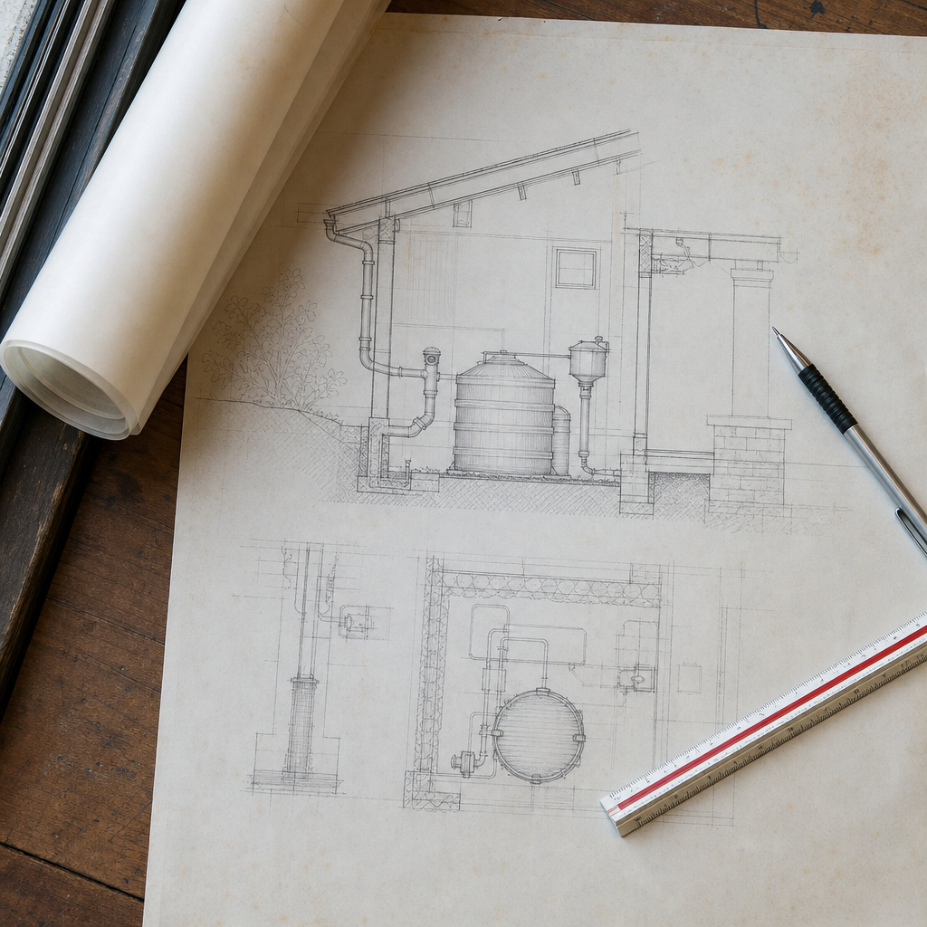
On residential sites throughout Austin, rainwater harvesting systems continue to evolve in complexity and regulatory oversight. For systems to move smoothly through the City of Austin’s permit process-and to actually pass inspection-every element of rainwater collection, storage, pumping, and non-potable distribution must be drafted on plan sheets with explicit clarity, full code citations, and robust coordination across plan disciplines. Austin’s 2024 Uniform Plumbing Code (UPC), International Residential Code (IRC), and Land Development Code (LDC), as amended locally and enforced by the Development Services Department (DSD), create a demanding technical environment for the drafter and designer. Approval hinges not only on engineered system performance, but on the completeness and compliance of drawing annotations, specs, and redline responses.
Drafting Code-Compliant Notes and Labeling for Non-Potable Residential Rainwater Systems in Austin
Required Code References: 2024 UPC Chapter 17 and Austin Amendments
Every non-potable rainwater system in Austin must be designed and documented according to the 2024 Uniform Plumbing Code (UPC) Chapter 17. Austin’s amendments, codified in City Code Chapter 25-12-152-the Uniform Plumbing Code Article, effective July 10, 2025-add further specificity. Systems with storage exceeding 5,000 gallons or connected to house plumbing require permits (cityrulelookup.com). All plans must call this out in the general notes:
- General Note Example: "ALL RAINWATER HARVESTING SYSTEM COMPONENTS THE SUBJECT OF THIS SCOPE SHALL BE INSTALLED PER 2024 UPC CHAPTER 17 AND CITY OF AUSTIN AMENDMENTS TO UPC (25-12-152), AND COORDINATED PER TECHNICAL CRITERIA MANUAL 2.9.2."
Clear System Labeling and Permit Sheet Notes
Code compliance in Austin depends on unambiguous labeling-on-site, on every plumbing riser, and on plan sheets. UPC 1701.8 and City Amendment Section 17-6 require signage at all non-potable outlets (hose bibbs, faucets, valve boxes):
- Label Call-Out Example: "ALL RAINWATER OUTLETS AND PLUMBING DEVICES TO BE LABELED ‘NON-POTABLE - DO NOT DRINK’ PER UPC CH. 17 & COA AMENDMENTS."
- ANSI Z535.4-2011 requirements for hazard signage may be referenced for label graphics.
Plans must show and call out non-potable outlets and location of required signage on plan, elevation, and detail sheets with dimensions from finished floor or grade to signage (typically 48" max). Plan review comments often flag missing or confusing system labeling, for example:
- “Label all rainwater hose bibbs as non-potable at plan.”
Written Notes and Code Citations
All plan-sheets, including the plumbing site plan, riser diagrams, and cover sheet legends, must cite relevant UPC and Austin amendments. A general note should include:
- UPC 1702.2-Requirement for non-potable outlet markers.
- UPC 1703.2-Materials for pipes and storage tanks.
- Austin LDC Chapter 15, Article 12-Local amendments.
- Reference to Texas Commission on Environmental Quality (TCEQ) §290.44 (for interface with potable water and auxiliary supplies).
Missed or vague notes are among the most common redlines found in Austin DSD plan review cycles.
System Layouts, Detail Sheets, Symbols, and Legends
Rainwater system layouts demand inclusion of (at minimum):
- Plan view of roof catchment areas with directional arrows and linear measurements.
- Routed conveyance piping (size, labeled as PVC SCH 40 or HDPE; call out diameter typically 3"-6" for residential).
- Location, size, and material schedule for cisterns.
- Ancillary equipment: first-flush diverters, sediment filters, UV sterilizers.
- Symbols for crucial items-call out “RWH” for rainwater hose bibb, “FILT” for filtration unit, etc.-with a legend on the title or plumbing sheets.
Dimensioned locations and finished elevations are required for all “above slab,” “below grade,” and “wall-mounted” elements. A sample plan note:
- “12” HDPE RAINWATER CONVEYANCE PIPE, TRENCHED MIN. 18” BELOW FINISHED GRADE, SLOPE 1/8”/FT - SEE DETAIL 6/P2.2”
Redlines will cite missing dimensions, wrong pipe slopes, or discrepancies between plans and details.
Detailed Drawing Requirements for Rainwater Storage Tank Siting, Foundations, and Ancillary Component Integration
Siting per Austin LDC Zoning and Setbacks: Plan-Sheet Content
Rainwater tanks are considered accessory structures in Austin. The Austin Land Development Code, Section 25-2-492, applies for properties in SF-3 zoning:
- Front setback: min. 25’-0” from property line
- Side setback: min. 5’-0” from property line
- Rear setback: min. 10’-0” from property line
- All tanks must be shown dimensioned to nearest property lines on site plans.
Drawings must also identify proximity to “Critical Environmental Features” (see LDC 25-8-92/93) and 100-year floodplain limits (per LDC 25-7-92). For any tank placed within the 100-year floodplain, flood elevation datum and tank finished floor or invert elevation must be keyed to benchmark and spot grade on the site plan. Common review note: “Demonstrate tank siting outside all required setbacks; provide finished floor elevation at 2’ above BFE, if within regulated floodplain.”
Foundations and Structural Detailing: Sheet Spec and Dimension Examples
Full cisterns impose significant weight: a 5,000-gallon tank exerts >40,000 lbs including water and tank mass. Drawings must include:
- Above-grade tank: reinforced concrete slab extending 12" beyond tank perimeter; slab depth and reinforcement per IRC Table R402.2 (min. 2,500 psi compressive strength concrete; typically shown 6" or 8" slab, #4 rebar @ 12" o.c. each way).
- Below-grade tank: “Tank section” detail cut at widest span, showing wall thickness, external hydrostatic loading, waterproofing membrane (ASTM D6135), and drainage board.
- Foundation plan: reinforced pad dimensions, anchor bolt call-outs, and cut-section reference, e.g., “SEE FOUNDATION DETAIL 4/S2.1”.
- Accessories: detail for access hatch (min. 24" diameter, lockable), ladder or platform if rim is >48" AFG (per OSHA 1910.27).
A common DSD review request: “Submit PE-sealed foundation details and calcs for above-ground tank support.”
Ancillary and Overflow System Detailing: Conveyance Drawings and Code Coordination
Overflow outlets must route excess water away from the building and prevent erosion or site flooding. LDC 25-8-211 requires discharge to stormwater management or pervious area; plans must note:
- “6” OVERFLOW OUTLET TO DRAINAGE SWALE, SLOPE 2% MIN., TERMINATE MIN. 6'-0" FROM FOUNDATION, W/ RIPRAP PAD.”
- Pipe slopes minimum 1/8” per foot for gravity drainage, per UPC Table 703.2.
Maintenance and access details, including accessible work area (min. 3’ clearance), must be shown in plan and section. All ancillary system materials must be scheduled (self-cleaning filters per manufacturer, pump types, UV sterilizer specs).
Precise Cross-Connection Control Diagrams and Potable Water Backup Schematics for Austin Residential Permits
UPC Chapter 6 and 17, City Amendments, and Austin Water Utility Mandates
Cross-connection prevention is a “fatal” code compliance topic in Austin. UPC Section 603 (Water Service Backflow Prevention) and Section 1702.6 (Non-Potable Cross-Connection Discovery and Control), reinforced by Austin Water’s program, strictly prohibit any direct tie between rainwater and potable lines.
- Detail all RPZ assemblies (Reduced Pressure Principle Backflow Prevention), required downstream of every city water meter and for every backup potable supply to cisterns (Austin Water).
- All cross-connection equipment must be listed on the City’s approved assemblies chart; outdated or unlisted devices draw immediate redlines.
Potable water make-up lines, allowed only to refill the storage tank (never direct to distribution), must show an air gap or approved RPZ assembly. Compliance must be dimensioned, such as:
- “VERIFY 2" AIR GAP AT POTABLE MAKE-UP TO TANK (UPC 603.3.4); RPZ LOCATED 12" DOWNSTREAM OF METER, 36" AFG, 24" CLEARANCE FOR SERVICING.”
Cross-Connection Diagrams, Symbols, and Sheet Conventions
Plumbing sheets must include riser diagrams or axonometrics with:
- Clear line weights (proposed bold, existing dashed), arrows, fixture/unit markers, and explicitly keyed device tags (e.g., “RPZ-1”, “AIRGAP-1”, “CHK-1” for check valve).
- Legend and schedule indexing each device reference, make/model, installation height, and maintenance note.
- Call-outs on the plan such as: “SEE DETAIL 3/P4.2: RPZ INSTALLATION AT WATER SERVICE.”
Sheet P2.1 or equivalent should display a one-line schematic with graphic conventions for “NO CONNECTION” between rainwater and potable inside the structure. All permissible make-up lines must be treated as supply-to-tank only, with “TO FILL TANK ONLY - MAINTAIN AIR GAP PER UPC 603.3.4, LOCAL AMENDMENT 17-6” in bold note format.
Missing or misplaced cross-connection controls are among the most frequent reasons for plumbing review rejection; expect redlines like: “Provide schematic demonstrating separation of rainwater and potable plumbing, with approved backflow prevention at potable supply.”
Device Specification, Sizing, Clearances
- All backflow and cross-connection assemblies on plans must be supported by manufacturer submittals and dimensioned installation clearances (typically 12”-36” AFG, 24” service access, referenced by detail).
- Pipe materials: only UPC-approved materials-Type K/L/M copper, CPVC, or PEX for potable lines; Schedule 40 PVC or HDPE for non-potable.
- Pipe diameters keyed to flow and fixture count (per UPC Table 610.3).
Schedules should itemize each assembly: model, capacity rating, listing agency, location by key plan grid, and testing/maintenance notes.
Electrical and Mechanical System Integration for Rainwater Pumping and Distribution on Residential Plans
NEC 2026, Mechanical and Plumbing Coordination
Determinative system elements-pumps, control panels, outdoor electrical feeds-must follow 2026 National Electrical Code (NEC) and both IRC/IBC mechanical requirements. All construction documents submitted after September 1, 2026, in Austin must demonstrate:
- GFCI protection for all exterior outlets and circuits that may serve rainwater pump controls (NEC 210.8).
- Outdoor-rated, weatherproof enclosures (NEMA 3R or higher for control panels, scheduled with make, model, ingress protection ratings).
- Equipment schedules on all M- and E-sheets, detailing model, capacity, amperage, and required disconnects. Example table:
| Equipment | Make/Model | HP | Voltage/Phase | Amps | NEMA Rating | Notes |
|---|---|---|---|---|---|---|
| Rainwater Pump | Goulds J10S | 1.0 | 120V/1PH | 13.8 | 3R | Continuous duty |
- Minimum branch-circuit ampacity calculations must be provided per NEC Article 430, with corresponding wire sizing and conduit specs cross-referenced to the one-line diagram.
Mechanical Coordination: Pump, Piping, and Valve Detailing
Pumps and distribution piping must be fully coordinated between mechanical and plumbing sheets, referencing all isolation, bypass, and test ports. Mechanical detail sheets should include:
- Connection diagram for suction/discharge; use “SEE DETAIL 2/M2.1” for pump installation section.
- Schedule 40 PVC or HDPE (for non-potable) above 1.5" diameter; note “UV-resistant” for any pipe exposed above grade.
- Isolation ball valves, union couplings, air bleed for priming, and test-tap takeoffs at filter outlets.
Every mechanical/electrical/plumbing (MEP) sheet set must show backflow prevention (RPZ) at any point where backup supplies interface, with call-outs and section cuts to installation details. A typical redline: “Add GFCI protection note at pump panel; callout and schedule NEMA rating per NEC 430.”
Protection Details, Materials, and Codes on Drawing Sheets
- All exposed electrical must be shown with code-compliant outdoor protection: “WEATHERPROOF GFCI-RECEPTACLE AT HEIGHT 18” AFG, W/ IN-USE COVER, PER NEC 406.9(B)(1).”
- Piping specified with dimension and ASTM listing (e.g., “2” SCH 40 PVC, ASTM D1785, UV SHIELD COATING”), with clear transition notes at points of connection.
- All electrical and mechanical call-outs must reference plan grid and detail cut, e.g., “SEE ELECTRICAL SITE PLAN, SHEET E2.1, GRID C4.”
Material specs tables should be placed on appropriate plan sheets with all system components scheduled, and each line item referencing manufacturer cut sheets submitted separately.
Navigating Austin DSD Plan Review: Common Redlines and Drawing Adjustments for Rainwater Harvesting System Submittals and Jobsite Call-Outs
Textbook Submittal Pitfalls and Reviewer Triggers
Austin DSD reviewers follow a strict set of review protocols based on the 2024 IRC, IBC, and local amendments. Key project risks include:
- Insufficient system detail-missing plan, elevation, or isometric for any component; incomplete legend or schematic.
- Non-compliance with setbacks or zoning overlays, such as siting in a required setback per LDC Section 25-2-492 or in a buffer to a Critical Environmental Feature.
- Lack of PE-sealed calculations for tank foundations or incomplete site grading info for tanks in the floodplain.
- Missing or inadequately specified cross-connection or backflow prevention devices.
These issues are reflected in commonly issued redlines:
- “Provide tank dimensioned location to all property lines; verify compliance with all required setbacks.”
- “Include structural details and calculations (sealed) demonstrating foundation capacity for full tank load.”
- “Demonstrate code-compliant separation and labeling at all non-potable outlets; cross-reference to approved detail sheet.”
Failure to address these topics at initial submittal level almost always leads to markups, delayed reviews, and extended correction cycles.
Austin-Specific Drawing Sheet and Submittal Expectations
Successful permit sets for rainwater harvesting must include:
- Site Plan (C or A sheets): Showing tank, piping, and critical dimensions to all property lines, setbacks, topographical or floodplain datum, PPE area if applicable.
- Structural/Foundation Sheet: Tank concrete slab or below-grade design must show reinforcement pattern, slab dimensions, material specs, cross-section with labeled detail bubble.
- Plumbing Plans and Schematics: Full sanitary and non-potable lines; riser or axonometric diagram, labeled device locations; schedule of cistern, pumps, filters, and cross-connection devices; typical call-out, “INSTALL RPZ ASSEMBLY (SEE DETAIL 2/P3.1).”
- Mechanical/Electrical Sheets: Equipment schedule for pumps/controls, one-line for supply circuit, GFCI call-outs, weatherproof enclosure notation.
- Materials and Equipment Schedules: For tanks: “5,000 GAL POLYETHYLENE CISTERN, 96” DIA x 130” H, NSF LISTED.” For pumps, filters, valves, and control units: manufacturer, model, continuous duty rating, voltage/phase/amp, installation reference. Example: “SELF-PRIMING PUMP, 1HP, 120V/1PH/15A, AUTO SHUTOFF, GOULDS J10S.”
- General and Sheet-Specific Notes: All relevant code citations, labeling requirements, and city amendments.
Correcting Redlines and Field Adjustments
- Clarify discrepancies between site plan and detail sheets-dimension labels must match throughout sheet set; e.g., if the tank is shown “5’ O.C. from S property line” on the site plan, details and sections must reflect same dimension.
- Add missed elevations and call out benchmark (BM) used for all vertical data (e.g., NAVD88 or assumed datum); include “BM=XXX.X’” on every site-related sheet.
- Update system schedules and device tags-incorrect or ambiguous “Backflow Preventer” must instead be labeled “RPZ-1, WATTS 009M2-QT, 1.5””, referenced back to city’s approved device list.
- On the jobsite, ensure field marking matches plan labeling; city inspectors will require physical labels in specified location and may require field measurements to match submitted plans.
The Architectural Plan Review Commercial Checklist (see here) remains essential to avoid inadvertent omissions or coordination failures between sheets and disciplines.
Across all sheets and systems-structural, plumbing, mechanical, electrical-full compliance with Austin-adopted code editions, city amendments, and permit review conventions is the only reliable path to project approval and successful rainwater harvesting system execution.
Kingsway Drafting & Design delivers precise, code-ready residential drawings for permit and construction across the United States.