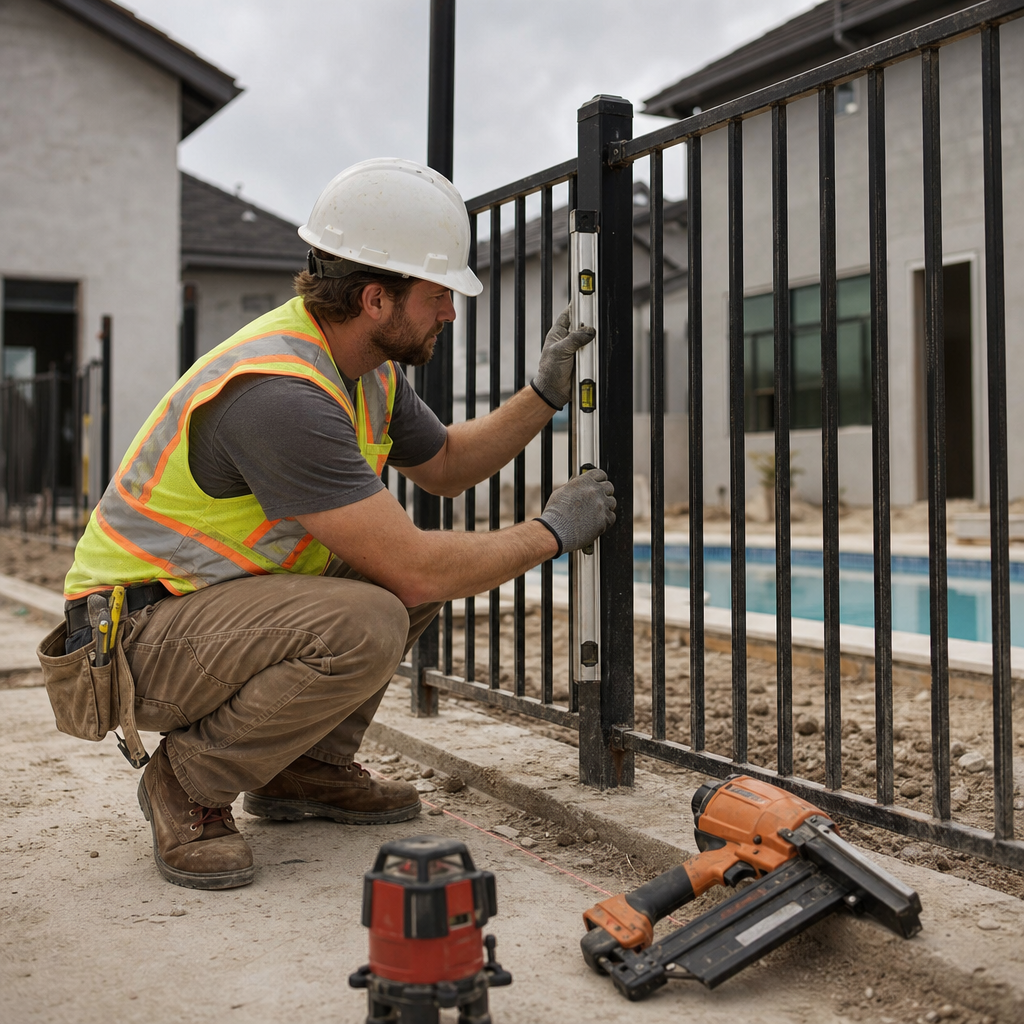
Dallas has adopted the 2021 International Swimming Pool and Spa Code (ISPSC) and the International Residential Code (IRC), with local amendments governing all residential swimming pools. Code-compliant pool barrier plans in Dallas must evidence unambiguous protection strategies, precise critical dimensions, and referenced code sections at every point of regulatory concern-from site-defined setbacks to activation protocols for door alarms. Both the Dallas permit workflow and plan-review conventions place a premium on drawing clarity, strategic annotation, and meticulous coordination between site, architectural, and specialty sheets.
Detailing Vertical Barrier Height, Clearances, and Non-Climbable Zones on Dallas Residential Site Plans and Details
Dallas Code Anchors and Local Amendments
Barriers enclosing pools must meet minimum criteria from IRC Appendix G Section AG105.2 and Texas Health & Safety Code Chapter 757, with additional control via Dallas's amendments (Dallas IBC Amendments, ISPSC §305). The Dallas Building Inspection (DBI) plan reviewers expect the following requirements fully dimensioned and referenced:
- Minimum Height: 48 inches, measured from grade on the side opposite the pool. See ISPSC 305.2, IRC AG105.2.1, and City amendments.
- Maximum Vertical Clearance at Bottom: 2 inches, measured from finished grade immediately outside the enclosure; 4 inches permitted if over a solid surface such as concrete. Grade per Dallas is the ground level next to the barrier-not at some distant datum-so slope must be considered when dimensioning (ISPSC 305.4.1).
- Maximum Opening in Barrier: Gaps or holes in the barrier may not allow passage of a 4-inch sphere (IRC AG105.2.1, ISPSC 305.2.2).
Common Dallas Plan-Review Redlines and Code Interpretation
- “Barrier shown at 44” AFF - revise to min. 48” per AG105.2.1.”
- “Gap under fence at northwest property line exceeds 2” - revise fence detail.”
- “4” sphere passes through pool picket spacing; specify and detail compliant infill.”
- “Provide non-climbable zone diagram at all proposed trees, equipment, utility meters within 36” of barrier.”
Misinterpretation of grade leads to under-built barriers along sloped sites. “Grade” is strictly the ground immediately adjacent to the enclosure (ISPSC 305.2.1). Site plans and fence details must document finish grade elevation at all barrier lines, especially where terrain transitions, requiring spot grades and fence step details.
Dallas code and permit reviews define climbable surface as any horizontal or diagonal element-fence rails, retaining walls, equipment pads, landscaping materials-within 36” horizontally of the barrier (ISPSC 305.2.9; Texas HS §757.004). Sheet annotations must dimension hardscape/landscape features in plan and flag for non-climbability. “No permanent fixtures, rails, equipment, landscaping, or similar climbable objects within 36” horizontal or 48” vertical zone exterior of the pool barrier (see Site Plan Detail 3/A1.02).”
Sheet Call-Out Examples and Detail Conventions
- “Min. 48” Barrier Height from Grade (AG105.2.1, ISPSC 305.2, Dallas Amend.)” positioned at every fence segment.
- Section callouts with “2” max vertical clearance (AG105.2.2); indicate slope and finished material at base.”
- Picket detail note: “Space pickets max. 4” clear; all welds ground smooth; see 5/A1.04.”
- Plan keynotes: “No equipment, steps, planter edges within 36” exterior side per ISPSC 305.2.9.”
Chain-link-while inexpensive-is flagged in Dallas as a frequent climb hazard unless mesh openings are reduced to a max. 1-3/4” and top rails are omitted or shaped non-climbable (NCTCOG IRC Amendments). Details must provide material type, mesh size, post embedment, and non-climbable termination at grade and at top.
All material descriptions (powder-coated tubular steel, solid masonry, non-climbable wood, etc.) as well as hardware ratings (corrosion resistant; see gate details below) belong on barrier detail sheets as direct cross-references to code, avoiding generic “by contractor” notes.
Comprehensive Gate and Access Point Detailing for Dallas Residential Pool Barriers
Criteria for Gate Operation, Hardware, Latch Heights, and Inspector Preferences
Gates are scrutinized tightly at plan review and inspection for hardware performance. Reference IRC AG105.2.8, Texas Health and Safety Code §757.004, and Dallas amendments:
- Self-Closing, Self-Latching Action: All gates accessing the pool must swing outward (away from water), return to closed position from any angle via self-closing mechanism, and automatically latch shut (IRC AG105.2.8).
- Latch Release Height: Release mechanism at least 54” above grade. Alternate: If latch is on pool side, mount at least 3” below top of gate and within a barrier with no opening greater than ½” within 18” radius of latch (IRC AG105.2.8.1; Health & Safety Code §757.004b; Dallas Building Code Amendments).
- Hardware: Corrosion-resistant, tamper-resistant, able to accept padlock or integral lock, per §757.004a2. See product submittal or detail reference-do not rely on “typ by others.”
Plan Review Redlines and City Expectations
- "Gate elevation and plan unclear - unclear if opens outward, please clarify swing and direction."
- "Self-closing/latching device not specified by mfr/model-provide hardware cut sheet or spec."
- "Latch location not labelled; detail release mech. at pool side if less than 54”."
Gate elevations are to show swing with an arc (arrow annotated “outward”), latch at 54” minimum, and section detail of self-closing and latching device. Elevation tags should call out: “Self-closing/self-latching hinge, 54” min. latch height aff (AG105.2.8; Health & Safety 757.004). Hardware: SS self-latch, corrosion resistant, padlock provision-see HWD-1 spec sheet.”
Specific Dimensions and Hardware Call-Outs
- Gate Height: Not less than 48” above ground at every point. For sloping grade, draw stepped gate bottom or adjust finished grade locally.
- Latch: “Locate release at 54” aff, or 3” below top and min. 18” shield (½” max opening) if on pool side.”
- Clearance: Maximum 2” under gate (more for hardscape only).
- Hardware: Stainless steel (SS) or powder-coated enclosures; self-latching action verified by physical cut sheet or dimensioned sketch. Field: “All fasteners corrosion-resistant; hardware to meet Dallas Amendments and Health & Safety 757.004.”
Spec sheets for hardware (D&D Technologies MagnaLatch, or equivalent) are to be referenced in the hardware schedule with actual product data provided, not simply “by contract.” Gate location tags should reference barrier plan sheet and section (e.g., “See 2/A1.03”).
Integrating Dwelling Walls into the Pool Barrier: Door Alarms and Window Criteria
Barrier Continuity, Alarms, and Window Protections
Dwelling envelope integration is the most common cause of disapprovals in Dallas plan review. When a wall forms part of the pool barrier, all doors and certain windows opening from the house into the pool must meet ISPSC 305.4 and IRC AG105.2.9 (with Dallas-specific height conventions per Dallas Swimming Pool and Spa Code):
- Door alarms: Every door opening from dwelling/unit to pool needs an alarm, listed per UL 2017, with at least 85 dBA intensity at 10 ft, sounding not less than 30 seconds (UL 2017 standard). Activate on door or screen opening.
- Deactivation switch: Positioned minimum 54” above threshold for non-accessible units, or 48-54” for Type A/B/accessible per local code adjustments.
- Doors as part of barrier: Alternatively, provide self-closing/self-latching doors at barrier wall. Must swing outward from pool-detail in plan and elevation.
- Windows: Operable windows with sill less than 48” aff (interior) must provide the same UL 2017 listed alarm as for doors, or use a permanently mounted fixed guard (per code), or other department-approved device. Non-opening or >48” aff = no additional alarm required.
Drawing Notation and Detail Conventions
- Key all dwelling-pool access doors with symbol (e.g., “DA” in hexagon) and note: “Door equipped with UL 2017 listed water hazard entrance alarm, min 85dBA/10’, 30s, switch 54” aff, per ISPSC 305.4, Dallas Amend.”
- Window schedule: Sill heights dimensioned for all pool-facing operable units, and alarms or guards called out directly next to units below 48”.
- Enlarged elevation/section for each door and window detail, indicating exact placement of deactivation switch (with bold “54”” or “48-54”” dimension arrow and section tag).
- General plan note: “All water hazard alarms listed per UL 2017; submit cut sheets at inspection.”
Common Dallas Redlines
- “Missing alarm device for Family Room French Doors; label UL listing and sound in keynotes.”
- “Window at 39” aff to pool deck not annotated for alarm-window schedule incomplete.”
- “Deactivation switch location unclear; show on reflected elevation.”
It is insufficient to simply note “alarms as required by code.” Drawings must directly specify the listing (“UL 2017”), sound and duration (85 dBA/10’, 30s minimum), and device mounting height at every device. Infractions at inspection typically result from missing deactivation height detail, ambiguous window notes, or non-recognized alarm models.
Specifying Non-Permanent and Temporary Pool Barrier Solutions for Dallas Permits
Details for Power Safety Covers, Automatic Covers, and Temporary Construction Barriers
For residential projects that propose a pool safety cover in lieu of a continuous fence, Dallas follows IRC AG105.2.7 and ISPSC Section 305.5, referencing ASTM F1346 for power-operated covers (Dallas IRC Amendments).
- ASTM F1346-rated cover: Drafting must explicitly state “Safety cover listed and labeled per ASTM F1346; submit cut sheet and installer affidavit at inspection.”
- Operation Mechanism: Covers may be automatic or manual, but must be lockable, operable by a key or code, and restrict unassisted entry. Drawing notes explain actuator location (“Activate/lock point at equipment pad, 54” aff min.”), and anchorage/track details must show sufficient embedment and anti-tamper function.
- Load Ratings: Keynote/legend: “Cover rated min. 485 lbs distributed load (ASTM F1346 7.1.2) to support two adults plus child.”
Temporary Construction Barriers and Jobsite Safety
During construction (after excavation, before final barrier), temporary pool fencing is a Dallas requirement-ISPSC 305.2.3 and State TAC §265.192. Details for temporary barriers must address:
- Material: Chain-link (1-3/4” mesh) or solid panels; plywood barriers also accepted. Notation: “Temp fence: 4’ min. height, posts 8’ o.c., anchored per detail 6/C1.02.”
- Height: Min 48” (same as final), unbroken until coverage is achieved via permanent enclosure or ASTM F1346 cover.
- Gates: If access is required, must be self-closing/latching, 54” latch height per permanent barrier code.
- Setbacks and Location: Fence to fully enclose all accessible pool areas, even partial shell. Plan note: “No gap in enclosure at any time; to remain until final barrier approved.”
Best drafting practice documents this with a “Temporary Security Fence Plan” sheet, phasing from temp to final in keyed note sequence: “Phase 1: Install temp fence per detail at edge of pool work; Phase 2: Replace with code-compliant permanent barrier after final construction inspection; No pool filling prior to final enclosure sign-off (see Dallas Pool Permit Notes GI-1).”
Common Redlines and Jobsite Inspection Triggers
- “ASTM F1346 compliance not labeled on cover detail-provide rating and lock actuation device location.”
- “Temporary fencing detail missing-add height, post type, mesh spacing; show on site plan.”
- “Gate access to jobsite must comply with latch height and swing direction.”
Inspections will require explicit affirmation (installer affidavit, physical test) that automatic or power covers meet load/locking and performance criteria. Absence of an unbroken temporary perimeter is a mandatory stop-work order per City inspector policy.
Dimensioning and Code Referencing Best Practices for Dallas Residential Pool Barrier Plan Sets
Site Plan and Zoning-Driven Constraints
Every pool permit in Dallas-across all residential zoning districts, including R-1/2ac and R-7.5-is screened for strict site placement and code compliance. Plan sets are expected to present:
- Property Lines and Easement Buffers: Show metes and bounds, explicit pool/barrier setbacks (often min. 5’ from rear/side, but confirm with local zoning map and plat restrictions; see Denison Zoning Example for regional precedent). Note any utility/drainage easements, which are not to be encroached.
- Pool, Fence, and Equipment Location: Provide scaled plan with all site structures, orientation, and north arrow. Annotate pool equipment (heater, pump pads) outside required setbacks, typically matching or exceeding the pool's.
- Topography: When grade changes, show proposed regrading and spot elevations at start and end of each barrier line.
Detail Sheet and Annotation Organization
- Barrier Details: Section details at every unique fence/gate conditions keyed from site plan (e.g., “See 1/A2.01 for Rear Iron Fence”). Indicate height dimensions, material, picket spacing, panel construction, and all fastener specs.
- Gate and Alarm Sheets: All unique gates must be called out (e.g., “G2 - Side Service Gate, see 3/A2.02”) with latch/closure hardware, swing direction, and lock details; alarm device mounting shown at all door access points per entry above.
- Integrated Code Notes: No standalone general notes. Every critical barrier/door/gate element is called out on plans/elevations directly with code section: “Min. 48” Barrier Height (AG105.2.1, ISPSC 305.2)”, “Gate swings out, self-latch at 54”, see AG105.2.8, 757.004”, etc.
Strategic Code Referencing and Dimension Practice
- Setback Dimensions: Every pool barrier dimension must close from property line-not just from face of house or deck. “Rear yard fence at 61.2’ from street lot line,” “Pool setback at 6.0’ min. from east sideyard” shown by dimension strings.
- Barrier Dimensions: “Pool barrier: 48” min. from grade per AG105.2.1,” “Gate latch at 54” aff per AG105.2.8,” “4” max. opening for all pickets, see section 1/A2.01.”
- Window/Door Notations: All house walls forming part of barrier are keyed to window/door schedules (“DA = Door Alarm, UL 2017, see AG105.2.9; WS = Window Sill confirmed >48” aff...”).
Dallas Permit Workflow and Plan Review Redlines
Permit submissions (“Pool/Fence Permit Package”) to DBI must include:
- Full site plan (scaled, with pool, setbacks, and easements annotated)
- Barrier and gate details keyed from site, each with material/spec/code callout
- Window/door alarm schedule, including UL listing reference for each unit below 48” aff
- Temporary fencing/cover/phasing sheet until completion and inspection of permanent systems
Common DBI comments:
- “Setback to property line dimension missing-add to plan.”
- “Gate details do not specify latch height or swing-correct per AG105.2.8.”
- “Alarm call-out missing on patio slider. Show alarm, UL listing, sound spec.”
- “Temporary pool security not shown from excavation to barrier sign-off.”
- “Barrier drawn through utility/drainage easement-confirm no encroachment.”
Zoning Districts (R-1/2ac, R-7.5) and Barrier Placement Impact
Zoning governs minimum rear/side setbacks, build-to lines, and accessory structure placement for every site. Pools and associated fencing cannot be placed within required setbacks or easements-in R-7.5, for example, 7.5’ side yards and 10’ rear yards are typical minimums. Fence heights and materials may also be otherwise regulated in certain districts (e.g., maximum height, sight-line restrictions at corners). Plan sets must tabulate each district’s numerical requirement and overlay pool and fence location with check-off matrix: “Pool = 6’ to East PL (OK); Barrier = 7.5’ min. at West (OK); Spa = 10’ to Rear (OK).”
Every plan reviewer is looking for setback, encroachment, and dimensional non-conformance at first glance-missing these will delay review and trigger resubmittal.
Material and Layout Specifications
- Barrier: Non-climbable, weather/rot-resistant materials. Chain link = 11 gauge, 1-3/4” mesh max per Health and Safety Code §757.004(c)(3).
- Fence posts: Embeds per structural detail, 24” min. or per fence product requirements, spec’d on detail sheet.
- All dimensions fully closed (layered from property line to pool, to building face, to barrier and back).
Conclusion
Comprehensive pool barrier drafting for Dallas means anchoring every detail, dimension, and hardware specification to the city’s ISPSC/IRC adoptions and amendments, with clear cross-referencing, robust phasing details, and annotated code callouts throughout all sheets. Only plans that clearly integrate code-derived heights, clearances, alarms, cover specs, and zoning setbacks-as documented and dimensioned-consistently pass DBI review and facilitate trouble-free inspections, from permit submittal to final occupancy. Kingsway Drafting & Design delivers plan sets aligned to Dallas enforcement reality, accelerating approval and jobsite execution.