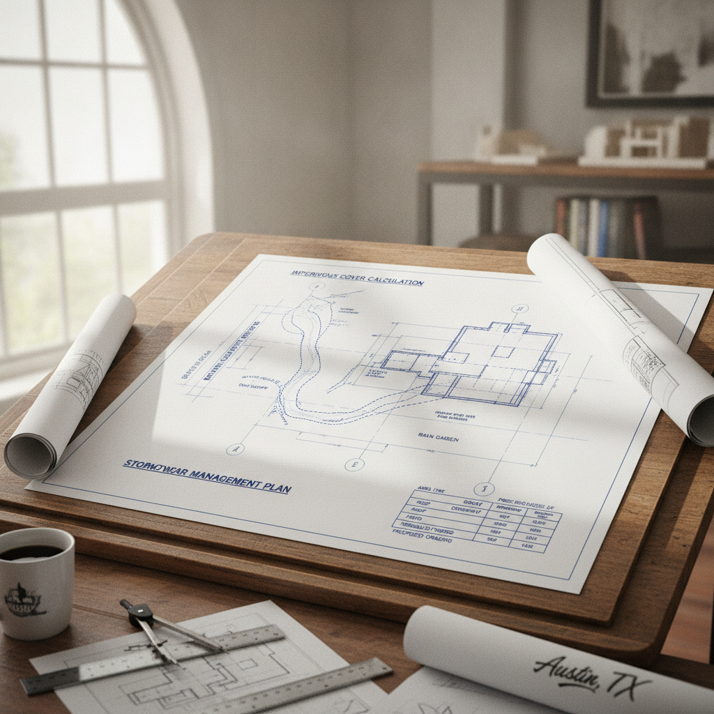
Impervious cover limits and on-site stormwater management (OSW) are rigorously enforced elements of Austin, TX residential permit sets. Austin City Code, reinforced by the Land Development Code (LDC), prescribes exacting standards for how impervious surfaces are measured, depicted, and validated, and for how drainage and OSW features are shown, dimensioned, and annotated. Development Services Department (DSD) reviewers expect both clarity and technical precision at every stage-from initial site plan to final as-built. Success in permit review, inspection, and long-term compliance depends not merely on broad code knowledge, but on applying local code amendments, correct details, and DSD’s presentation conventions directly into construction documents.
Drafter’s Guide to Impervious Cover Calculation Sheets and Zoning Compliance in Austin
Impervious Cover Inclusion and Exclusion Criteria per Austin City Code 25-8-63
Plan sheets must account for every impervious surface as defined by Austin City Code § 25-8-63. Per the code, impervious cover encompasses “roads, driveways, parking areas, buildings, concrete surfaces, and other impermeable constructions covering natural land surface.” The code further classifies the following as impervious:
- Areas surfaced with concrete, asphalt, or asphaltic products.
- Uncovered wood decks with drainage spaces-counted as 50% of area.
- Storage areas for scrapyards, salvage, and similar uses.
Explicit exclusions (do not count toward lot coverage):
- Sidewalks in public ROW or easements.
- Public multi-use trails, drainage swales, or conveyances not in the building envelope.
- Water quality and detention basins-except subsurface forms.
- Surface areas of ground-level pools, fountains, and ponds.
- Gravel areas over pervious soil for landscaping or pedestrian use (not compacted base).
In ambiguous cases, code reference must be called out on the cover sheet table or as keyed notes (e.g., “Gravel area X not included per LDC § 25-8-63(C)(7)”). For wood decks, the calculation must show “Deck at 50% area per LDC § 25-8-63(A)(3).”
Measurement Techniques and Impervious Cover Tables
Accuracy in area quantification is critical for compliance. The Environmental Criteria Manual (ECM) Appendix 1.8.0 and Section 1.8.1 specify calculation procedures. Each surface should be distinctly hatched and labeled on the Site Plan (A1.0/A1.1 sheets). Requirements for the calculation table include:
- Type of surface (roof, walk, drive, deck, patio, etc.)
- Material (asphalt, concrete, pavers, wood, etc.)
- Plan area (square footage, decimals to tenths or hundredths)
- Percent inclusion (full, 50%, or 0%) with code reference where not 100%
- Total IC area and lot size, computed percent IC
DSD plan reviewers routinely redline sheets for “incomplete area table,” “missing calculation for deck,” or “nonstandard justification for pervious exclusion.” The table should cross-reference each hatched area with a key or bubble on the site plan. All figures are typically rounded to at least the nearest tenth of a square foot.
Common Residential Zoning IC Limits (SF-1, SF-2, SF-3, RR)
- SF-1 (Single-Family Large Lot): 40% max impervious cover by lot area.
- SF-2 (Single-Family Standard Lot): 45%
- SF-3 (Family Residence): 45%
- RR (Rural Residential): 25%
Limits for every lot must be shown alongside the calculated impervious cover percentage. For instance: “IC provided = 2,488 SF (43.9%). Limit for SF-2 zone per LDC § 25-2-492: 45%.”
PUDs, Overlay Districts, and Special IC Rules
Overlay zones and Planned Unit Developments (PUDs) often introduce unique IC maximums or calculation bases that supersede standard code. Drawing sets must cite the specific PUD or overlay ordinance and show the corresponding IC limit table or summary. DSD reviewers regularly require note references, such as “PUD-specific IC restriction, Ord. YYYY-NNNN, per approved PUD Agreement, supersedes LDC Table 25-2-492.”
Presentation and DSD Plan Review Comments
Typical DSD review “markups” or comments for IC include:
- “Verify areas for all patios and decks; show dimensions.”
- “Provide evidence for exclusion of sidewalk”-with code citation.
- “Correct total IC. Figures provided don’t sum to table total.”
- “Cite code reference for PUD limits or overlays.”
Tables must be legible, placed near the main Floor Plan excerpt or Site Plan, and keyed with on-sheet hatches, colors, or area tags. All dimensions should appear on working layers with final values output on published PDF or plot sets.
Annotating Site Plans for Austin’s Drainage Requirements
Mandatory Spot Elevations (Building Corners, Property Lines, Swales)
Per LDC §25-7-92(C)(1), finished floor elevations are required to be two feet above the 100-year floodplain elevation. Plans must show spot elevations at every primary building corner, as well as at each break in grade along property lines, driveway aprons, swale inlets/outlets, and drainage features. Typical conventions:
- “FFE (Finished Floor Elevation): 628.34’ (NAVD88)” at all building corners
- Property Line Spot Elevations: “627.20’ PL @ NE” to “627.10’ PL @ NW”
- Swale/ditch inverts: “INV: 626.75’ start,” “INV: 626.20’ end”
If any corner is less than two feet above the floodplain, reviewers will redline “FFE does not meet LDC §25-7-92(C)(1)-adjust site grading.”
Depicting Existing vs. Proposed Contours and Drainage Flow Arrows
ECM 1.2.0 mandates clear distinction between existing and proposed grading:
- Existing contours: dashed 0.35mm (grey or black)
- Proposed contours: solid 0.5mm (black or color, e.g., brown)
- Spot elevations: shown in rectangular or oval markers, with plan callouts
- Drainage arrows: heavy head block arrow, minimum 1/8” width, along every surface swale, drive, or patio. Direction must demonstrate flow away from structures and toward designated outfalls.
DSD frequently redlines “no drainage direction shown,” “existing/proposed grading not differentiated,” or “missing spot elevations at grade break.” Contour intervals for residential lots typically not greater than 1 foot.
Dimensioning Swales and Berms; Symbol Library for Drainage Features
All proposed drainage improvements are to be fully dimensioned:
- Swales:
- Bottom width: 2'-0" (min. residential, confirm by flow calc)
- Depth: 6"-12" (per grading calc and ECM Section 1.2.0)
- Side slopes: 3:1 maximum (horizontal:vertical) for stability
- Longitudinal slope: 1% min. (
S = 0.01 x Length)
- Berms:
- Height: 1'-0" typical, varies by catchment and code case
- Base: 4'-0" minimum, 4:1 slopes for mowable side
All features are required to use ECM/DSD symbols including:
- Catch basins: rectangle with cross (DSD symbol STD-21-100)
- Manholes: circle with “MH” label
- Culverts: rectangle, directional arrows
- Swales: dashed centerline, solid edges, with flow arrows
- Berms: solid, hachured downhill edge
Legend on the sheet must decode all symbols. Nonstandard symbols or missing keys are routinely redlined, e.g., “add drainage legend,” “standardize swale symbol.”
Response to DSD Plan Review on Drainage
Common markup comments include:
- “Swale dimensions missing-provide bottom width, side slopes, and grade %.”
- “Drainage arrows not indicated-show positive drainage away from building.”
- “No verification of elevation at property line-show for neighbor protection.”
These comments require drafters to consult ECM and DCM, and to provide appropriate notes, details, or sheet references.
Drawing Standard Details for Austin’s On-Site Stormwater Management (OSW) Strategies
Rain Gardens (Bioretention Areas): Section and Plan View Detailing
Rain gardens are regulated by Appendix A, Section 1.6.0 and Appendix F of the Austin City Code, with detail protocols elaborated in the ECM.
- Soil layers: Engineered mix-50-60% sand, 20-30% topsoil, 10-20% organic matter. Thickness and stratigraphy to be dimensioned in section (“12” min. bioretention mix per ECM 1.6.0 Fig A-3”).
- Mulch: 2-3” shredded hardwood over top.
- Depth: 6-12” typical for residential bioretention, called out on section/elevation.
- Plan area: Calculated by drainage area - shown in key table with cross-reference note: “Rain garden RG-1: plan area = 120 SF, captures 1,400 SF rooftop and patio.”
- Overflow: Pipe or weir, with invert elevation and destination (e.g., “OUTLET: 627.20’ to swale SW-2”).
Plan sheets must reference ECM section and include plan call-out, section cut arrows, and leader notes (“DETAIL: Rain Garden, see A5.2/S5.2”). All plantings should be noted by code-required native or adapted species list. Reviewers redline “missing overflow device,” “rain garden section does not match grading plan,” or “engineered soil spec not indicated.”
Permeable Pavement System Details
- Pervious surface layer: Interlocking pavers, pervious concrete or porous asphalt, called out by manufacturer and type (“Belgard EcoPriora, color XX”).
- Aggregate base: “18” min. washed aggregate (AASHTO #57, 1.5-2.5” dia.)”-dimensioned in section view along with separation geotextile (e.g., Mirafi 140N).
- Slope: Not to exceed 5% for infiltration effectiveness, indicated on plan (“Surface slope: 2% to street swale”).
- Underdrain (if required): 4” perforated SDR-35 PVC @ 1% slope, invert elevation and cleanout locations dimensioned/hatched.
Cross-referencing notes such as “DETAIL: Permeable paving, see C6.2,” are needed on the site/grading plan. Each section must list material specs and manufacturer’s information for DSD approval. Omission of underdrain, aggregate spec, or cross-reference commonly triggers redline comments.
Dry Well Section/Plan Standardization
- Well structure: 48” dia. precast concrete or HDPE, perforated wall. Section must show depth (e.g., “6’ min. to invert”), surrounded by “12” min. clean washed gravel (ASTM #57).”
- Inlet/outlet: Pipe inlets dimensioned and located with structure, “Overflow: 4” SCH-40 @ 1% to BI-2.”
Plan set must extract each OSW feature onto a detail sheet, call out required depths, pipe diameters, invert elevations, and material standards. Include note: “All SWM structures per ECM App. F; install per manufacturer recommendations and City of Austin standard details.”
Integrating Austin City Code References and Regulatory Notes on Permit Drawings
Citing Austin City Code and LDC on Drawings
Key code references must be integrated into general notes, sheet legends, and annotations. Examples:
- “Impervious cover calculations in accordance with LDC § 25-8-63 and ECM Appendix 1.8.0.”
- “Water quality controls designed per LDC § 25-8-213 and ECM Item 1.3.4.2.”
- “All SWM features to treat first 0.5” runoff event per LDC § 25-8-213(B).”
These are added to the General Notes (G0.1), Site Plan notes, or as text call-outs near relevant features. Where overlays or PUDs affect IC, add: “IC limit per PUD Ordinance YYYY-NNNN supersedes LDC Table 25-2-492.”
Boilerplate Language for SWM and Impervious Cover Compliance
DSD expects boilerplate declarations on each permit set:
- “Impervious surface area limits have been calculated and are in compliance with City of Austin LDC § 25-8-63 and ECM 1.8.0.”
- “All SWM features designed and constructed per ECM App. F and DCM requirements.”
- “Erosion and sedimentation controls shall conform to LDC § 25-8 and ECM as applicable.”
Plan reviewers may redline: “add LDC/ECM reference in notes,” or “general notes missing applicable SWM references.”
Design Parameters for SWM Features: Drawing and Notation
- For each SWM device, note design storm event: “Treatment volume is based on 0.5” over contributing IC per LDC § 25-8-213(B). Storage provided: 75 CF, treating 0.5” from max IC.”
- All features to “provide at least the treatment level of sedimentation/filtration per LDC § 25-8-213(A)(1).”
- Overflow and maintenance: “Controls are accessible for maintenance and inspection, meeting ECM requirements.”
In response to DSD plan review comments, supplement with summary tables showing design storms, contributing area, and capture volume for each SWM feature-in both tabular form and annotated on sheet.
Call-Outs, Legends, and Sheet Conventions
- Leader call-outs to code notes-e.g., “SEE NOTE 5: LDC § 25-8-63 compliance.”
- Section/detail bubbles: “SEE DETAIL 4/A5.3”-cross-referencing all SWM feature details.
- Legend: Decodes each site grading, SWM, and IC symbol (“IC - impervious cover hatch,” “SW- Swale centerline,” “BIO - bioretention outline”).
Redline comments for this aspect typically read, “legend incomplete,” or “details unreferenced on plan.” As-built drawing revisions must retain all updates in title/revision block with code references intact.
Jobsite Verification and As-Built Requirements for Stormwater Management in Austin
Critical Dimensions for Field Verification
- Rain garden excavation: Survey for “12” min. bioretention media thickness, verify finished grade per plan (e.g., “top of RG-1 at 627.50’, per A5.2”).
- Permeable paver systems: Base thickness (sub-base, base, bedding) measured at 6”, 8”, 2” minimum, as specified on details. DSD field inspectors carry probe rods and will write up “Paver base below 8” min. per details.”
- Weir, underdrain, and overflow elevations: Surveyed to hundredth foot, checked against plans (“Weir invert at 627.22’, built at 627.24’-accept with notation if within 0.05’ tolerance, otherwise flag for correction”).
Documenting Field Changes and As-Built Drawing Protocol
Deviations from approved plans are usual in the field; prompt documentation is required:
- Field change log: For any modification (e.g., revised rain garden size, shifted swale), mark on a copy of the most recent plan set and annotate with date, brief description, and initial.
- RFI Process: Submit revised detail to engineer/DSD, obtain approval before continuing critical SWM work.
- As-built drawing update: Reflect all accepted changes, update title block “As-Built Revision YY-MM-DD, clouded.”
As-built sheets must show all SWM feature dimensions as constructed, all invert and surface elevations, all drainage patterns as graded, and must be sealed if surveyed. DSD may request the as-built in both PDF and CAD for audit.
Post-Construction Survey Requirements
After construction, a licensed surveyor must provide:
- Impervious cover survey: All drives, walks, patios, etc., measured to the current built edge. Final IC calculation table to be included on as-built “Site Plan As-Built” sheet.
- SWM feature survey: In-place location, width, length, depths, invert elevations of all rain gardens, permeable systems, swales, and dry wells-tied to site benchmarks (“Finish floor, planters, overflow grate at 627.30’, etc.”).
These forms must be submitted to DSD prior to final inspection or Certificate of Occupancy. Failure to provide causes DSD comments: “No as-built for IC/SWM-submit surveyed drawings.”
DSD Final Inspection Checklist: Stormwater Functionality
- “All temporary erosion controls removed, permanent stabilization established.”
- “Bioretention areas vegetated per plan; mulch intact, overflow functional.”
- “Pervious paver surface clean and jointed, base thickness confirmed.”
- “Overflow and maintenance access as per plans.”
- “Drainage patterns match as-built/existing spot elevation survey.”
Major discrepancies between plans and field are flagged: “Swale not constructed to grade-correct and resurvey.”
Importance of As-Builts for Maintenance and Audits
Accurate as-built documentation is not merely a closeout step; future SWM function and city audit depend on reliable dimensional records. All maintenance, re-inspection, or redevelopment will reference the as-built “Site Plan As Constructed” and detailed features sheets. As-builts provide liability protection, ensure compliance for subsequent owners or property managers, and are enforceable records in the event of IC overage or stormwater failure complaints.
Drawing Sheet Call-Outs, Conventions, and Integration with Codes
Title Block, Legends, and Revision Blocks
Standard practice across Austin requires:
- Title block with project location, permit #, sheet #, date of issue, and as-built date if revised.
- Legend covering every hatch, line, spot elevation, and drainage symbol-matching DSD/ECM standards.
- Revision block recording clouds, changes, and dates. Each DSD mark-up or field revision must be updated through as-built.
Detail Callouts and Cross-References
- All SWM feature locations reference detail sheets: “SEE DETAIL 3/C5.1,” “SEE A5.2 for rain garden section.”
- Call-out notes to storm events, IC calcs, code references: “Treatment for 0.5”/IC-see Note 7.”
Improper referencing or lack of detail bubble consistency routinely delays DSD approval. Drawing package organization (cover, general notes, site/grading plan, SWM details, specification sheets, and as-built) is critical to create an auditable trail from planning to closeout.
Dimensions, Material Specifications, and Code Citations in Drawing Annotation
- Decks: show “50% inclusion in IC, 0.5 x [plan area: XX SF] per LDC § 25-8-63(A)(3).”
- Rain gardens: “12” min. engineered mix, see ECM App. F. Overflow weir at 627.22’±0.05’.”
- Swale: “2’ bottom width, 6” depth, 3:1 side slopes, 1% min. longitudinal, grass or native vegetative stabilization” on grading sheets.
- Permeable pavers: “18” #57 aggregate base, 8” concrete border, surface slope ≤5%, underdrain per ECM App. F permitted if required by soil percolation test.”
- PUD/overlay: “Limit per [specific ordinance]-supersedes base zoning.”
All dimensions, areas, slopes, and material ratings (ASTM, AASHTO, manufacturer, etc.) must appear directly on details, not only in schedules or specifications, for permit review and construction.
Conclusion
Success in Austin residential permit sets depends on combining detailed, code-cited impervious cover calculations with rigorously dimensioned and depicted stormwater features. Plan sheets must reflect both the nuanced requirements of Austin’s LDC, ECM, and DCM, and the analytical conventions preferred by DSD reviewers. As-built and jobsite protocols assure compliance at inspection and into ongoing operations, ensuring lasting environmental performance and regulatory security. Kingsway Drafting & Design delivers expert drawing packages and code compliance for Austin and the broader US residential market.