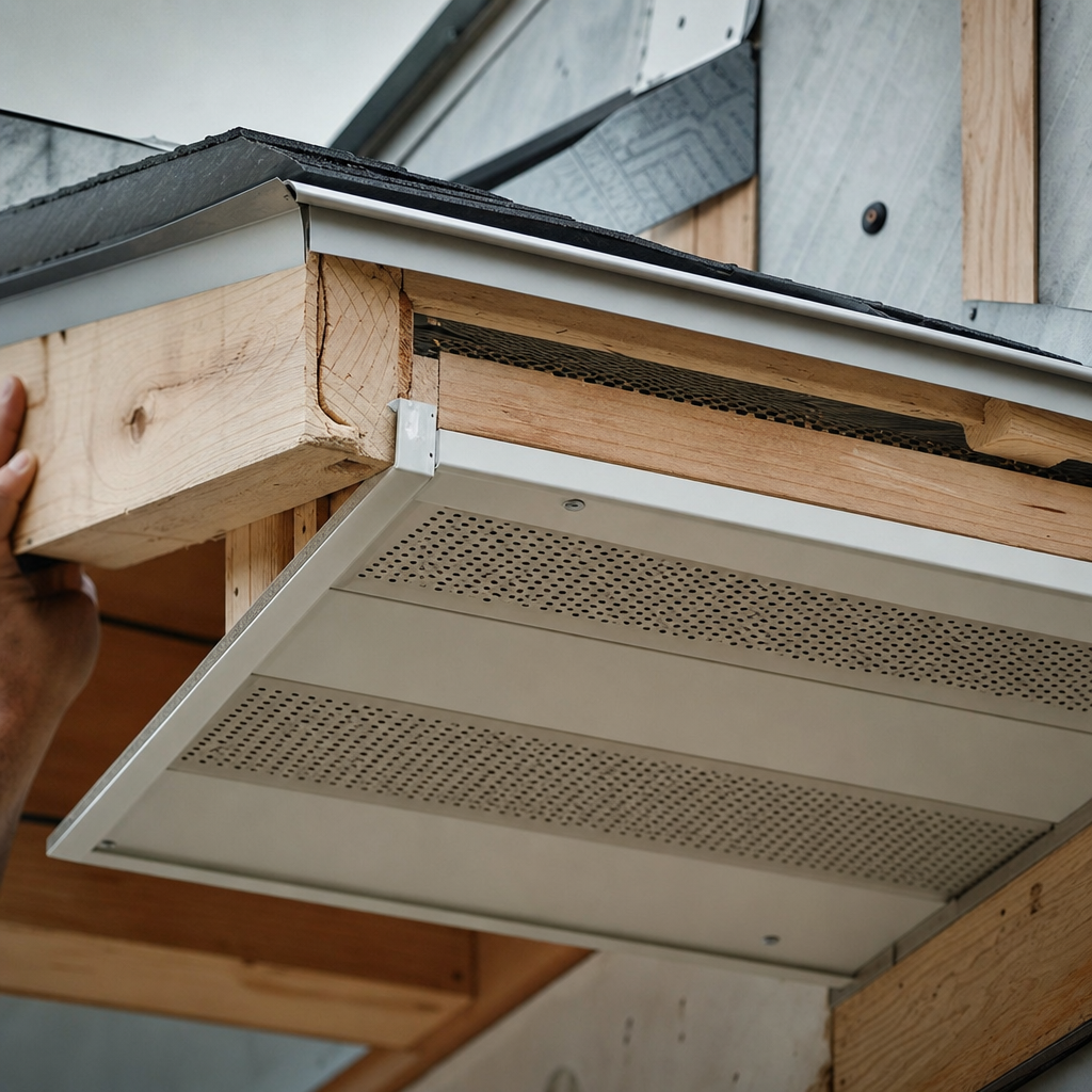
The Florida Building Code (FBC) 2023, with City of Tampa amendments, imposes rigorous criteria for high-wind resistant soffit and fascia systems in residential permit plans. Jurisdictional requirements in Tampa respond directly to exposure to hurricanes and intense wind events, demanding high standards for fastening, load path continuity, bracing, ventilation, and precise material selection. On construction documents, plan reviewers expect detail and clarity-omission of code-driven fastener schedules, failure to specify material pedigree, or lack of load path information invites redlines and departmental delays. Wind resistance, code citations, ventilative performance, and manufacturer compliance must be evident in both the narrative and the dimensioning/delineation of detail sheets.
Code-Compliant Fastening Schedules & Load Path Detailing for Soffit Systems in Tampa, FL
Section R704 of the Florida Building Code, Residential (8th Edition, 2023), as adopted by the City of Tampa, establishes minimum requirements for the installation and fastening of soffits in high-wind regions (FBC R704). The City’s Code of Ordinances Chapter 5 further incorporates local environmental considerations. Plan reviewers in Tampa scrutinize these details for compliance, emphasizing both prescriptive dimensioning and narrative call-outs directly on sheet sets.
Wind-Driven Fastening Schedules
Per FBC R704.1, exterior soffit assemblies must resist component and cladding loads for walls, using an effective wind area of 10 square feet-a critical sizing metric to apply in section and detail sheet calculation columns. Fastening must be designed for the exact wind design pressures called out in the permit set wind load summary; for much of Tampa, ASCE 7-16 wind speed maps and Exposure C conditions dictate requirements over 30 psf.
- Vinyl and Aluminum Soffit Panels (FBC R704.3.1, R704.3.3):
- Manufacturer-specified nails or staples: corrosion-resistant (aluminum, galvanized, stainless steel, rust-resistant coated)
- Fasten at both ends to secure support elements (nailing strips, fascia, subfascia)
- Spans over 16" require intermediate nailing strips (12" typical in high-wind areas)
- Drawing call-out: “Fasten 0.019" aluminum soffit panel at each end to wood nailing strip using stainless #8 x 1¼" screws 12" o.c.; intermediate strips at 12" max unsupported span”
- Fiber-Cement Soffit Panels (FBC R704.3.2):
- Minimum ¼" thick, ASTM C1186 Type A, Grade II
- Fasten per manufacturer's ICC-ES report, usually #8 x 2" screws, 12" o.c. perimeter, 16" o.c. field, into solid blocking
- Panel ends fully supported; all joints over framing
- Typical call-out: “1/4" fiber-cement vented soffit board, ASTM C1186 Type A, min Grade II, over 2"x4" wood nailer, fasten w/ #8 x 2" SS screws 12" o.c. perimeter, 16" o.c. field”
- Hardboard and Wood Structural Panels (FBC R704.3.4):
- Hardboard: Minimum 7/16" thick; 2.5"x0.113" siding nails, 6" o.c. at edges, 12" o.c. int.
- Wood panels: Minimum 3/8" thick; 2"x0.099" nails, identical spacing
- Must demonstrate wood species and grade in material note (“APA-rated OSB sheathing, 3/8", Exposure 1”)
During plan review, common redlines in Tampa include “Provide fastener type/size/spacing at soffit,” “Intermediate nailing strip missing for span,” and “No substantiation of code wind load resistance at vented panels.” Sheets must show a dedicated soffit fastening schedule table, with references to typical detail call-outs and tiebacks to FBC/ASTM language.
Continuous Load Path Illustration and Code Compliance
Beyond note and schedule, load path continuity-transmission of wind forces from soffit assemblies into the primary structure-must be explicit. This is particularly scrutinized along eaves, corners, and exposed gable returns where uplift and suction converge. Detail sheets should include diagrams or 3D isometric breakouts showing:
- Soffit panel attachment (panel-to-nailer and nailer-to-truss/blocking interface)
- Blocking arrangements: 2"x4" nailers, ladder or cantilever framing
- Fastener embedment depth (typically 1½" minimum into framing or as per product approval)
- Reference to wind uplift load transfer (call-out: “Provide continuous 2"x4" nailing, anchored each 48" max to wall plate with Simpson LTP4 or approved hurricane strap, verify w/ truss layout”)
Lack of continuity details triggers City of Tampa review notes: “Clarify soffit load path to structure,” “Show attachment schedule for 2"x4" soffit nailers,” and “Provide uplift calculation referencing FBC.” Cross-referencing detail sections (e.g., A-5/7.2, “Enlarged Soffit Section at Eave”) is standard practice.
Detailing High-Wind Resistant Gable End Overhangs and Fascia Attachments for Tampa, FL Residential Permits
Gable end overhangs present critical vulnerabilities in Tampa wind zone construction. Section R602.3 and R704.4 of the IRC (as adopted by FBC and City of Tampa amendments) regulate gable end wall bracing, overhang framing, and fascia installation. Plan sheets require bracing diagrams, annotated fastener details, and dimensioned assemblies to pass review in this jurisdiction.
Gable End Bracing, Outlookers, and Anchor Detailing
Continuous studs must extend from sole plate to roof sheathing (IRC R602.3); discontinuous stud layouts are not accepted. Blocking and sheathing tie into these studs-with the minimum sheathing thickness at 7/16" OSB (see Building America Solution Center). For gables exceeding 10' in height, IRC R603.3.1.1 requires explicit anchoring specifications:
- All gable end truss bracing shown
- Solid blocking between end truss and wall below, with continuous straps (Simpson H10 or equivalent) from truss to load-bearing plate
- Anchor wall to foundation with prescribed anchor bolts or straps
Overhangs (IRC R704.4.1) exceeding 12" must use cantilevered outlookers-dimensioned on sheet at 2"x4" or larger, 16" o.c., max 24" cantilever. Ladder framing required for overhangs up to 12", showing interlock with both the gable end and adjacent standard trusses. Drawings include section cuts: “Cantilevered outlooker: 2"x6" SPF #2, 24" o.c., extend min. 24" over plate, fasten to gable with (2) 16d nails + Simpson LSCZ/LRU hanger”.
Plan review redlines: “Show gable end wall bracing,” “Bracing schedule missing for outlookers over 12",” “No metal strap schedule shown.” The expectation is that structural detail sheets call out all connector types, embedment, and spacing-especially in the critical first three bays from the windward edge.
Fascia Attachment and wind-Resistant Fastening
IRC R704.4.1.2, as reflected in FBC and City interpretations, mandates for aluminum fascia:
- Design wind pressure > 30 psf: 1¼" finish nails, spaced no more than 16" o.c., in return leg and below drip edge
- Utility trim with snap locks spaced 6" o.c. permitted as alternative
- All installations per manufacturer's product approval (often cited directly by NOA or FL# in general notes)
Drawing/sheet notation: “0.024" aluminum fascia cover, white baked enamel finish, attach return leg and drip edge with SS finish nails, 16" o.c.; see detail F-2/A7.4”. For vinyl, call out the color, thickness, and requisite support blocking; all details reference installation per published manufacturer guide and project-specific wind design data.
Tampa reviewers routinely flag: “Fascia fastening not per code,” “Show nail spacing at both legs,” “Aluminum wrap must cite FL# approval.” All products and fastening layouts must be consistent between sheet notes, schedule, and manufacturer sections-call out all connectors by part number where pre-engineered.
Integrating FBC Ventilation Requirements (R806) with Wind-Resistant Soffit Vent Details for Tampa, FL
The FBC Section R806 governs attic and roof ventilation, while R704 and local amendments demand wind resistance at all vent openings. Success in construction documents means fusing these two requirements at every soffit vent detail.
Minimum Vent Area Calculations and Placement
Per R806.2, the net free ventilating area for attics is minimum 1/150 of attic floor area, or 1/300 with balanced intake/exhaust and vapor retarder on the warm-in-winter side. Exhibit calculations on plan sheets:
- “Attic floor area: 1800 SF x 1/150 = 12 SF (1,728 in²) required net free area total”
- “8 SF (1,152 in²) at lower (soffit) vents, 4 SF (576 in²) at upper (ridge/roof) vents”
Common review redline: “Demonstrate code vent area and distribution for attic.” All vented soffit details must call out both linear feet and per-panel net free area to validate ratios. Drawing notation: “Vented aluminum soffit, 0.032", 8 in²/LF net free area, total 90 LF eave yields 720 in² (6.0 SF) per side”.
Wind-Driven Rain and Wind Resistance at Vents
Tampa’s enforcement under wind-threat includes explicit resistance to both wind pressure and rain intrusion (reference testing to TAS 100(A) where available). Typically, this means:
- Vented soffit panel openings: least dimension 1/16" to 1/4"; larger openings protected with 1/8" mesh, stainless or PVC-coated
- Product approval: “Soffit panel: ATAS Wind-Lok MPV, TAS 100(A) tested for wind-driven rain; see Product Approval FL #XXXXXX”
- Fastening: As for solid panels; intermediate nailers mandatory at spans over 12"
Sheet detail includes expanded callouts: “Install vented panel w/ no opening exceeding 1/4"; bug screen min 1/8" mesh SS wire, secured behind vent flange; maintain continuity of eave blocking behind vent.”
Clearance, Obstructions, and Insulation
FBC R806.3: Maintain at least 1" airspace between insulation and roof sheathing adjacent to vent. Obstructions-blocking, insulation, baffles-must be indicated in detail sections (see “Eave Section w/ Ventilation Baffle, Detail B5/A7.2”). Call-out: “Rigid insulation baffle, min 1" gap over eave, fastened to truss top chord with (2) 8d nails.”
Reviewers frequently redline: “Show insulation stop at eave,” “Provide details at all vent terminations.” For spray-foam applications or unvented conditioned attics, explicitly reference and dimension “Unvented attic assembly per FBC R806.5, closed-cell foam to 5½" nominal, R-30, vapor-impermeable.”
Drawing Sheet Mechanics and Plan Review Navigation for Soffit/Fascia Details in Tampa, FL Permit Sets
The mechanics of drawing production, sheet organization, and notation take on greater significance under Tampa’s plan review regime. The FBC-mandated wind resistance, material durability, and ventilation must be evident not only in general notes or schedules, but directly at detail sheets, sections, and narratives.
Sheet Organization and Cross-Referencing
- Dedicated Detail Sheets and Call-Outs: All soffit/fascia conditions merit unique keyed details (e.g., Eave: Section E7/A6.2; Gable: Section G11/A6.5), each referenced on both plan and elevation views. Avoid “typical” notes unless every occurrence is truly identical.
- Fastening and Material Schedules: Tabulate every major soffit and fascia finish with code reference (“See Soffit Schedule, Sheet S-2 for fastening per FBC R704.3.2”). Tie details to specific schedule line items.
Common redlines: “Indicate referenced detail number on relevant elevation/section,” “Schedule does not match call-out on section,” “Lack of cross-reference between plan and eave/gable section.” Construct sheets so the plan reviewer can trace a continuous thread from general note to plan to section to enlarged detail without ambiguity.
Code and Product Approval Citations
Include explicit code section, even on details, where possible:
- “Install 1/4" fiber-cement soffit panel per ASTM C1186 (FBC R704.3.2)”
- “Vented aluminum fascia, compliant to FBC R704.4.1.2, product approval FL#####, installed per manufacturer's NOA”
Note manufacturer’s installation reporting (by ICC-ES, Miami-Dade NOA, or Florida Product Approval #) directly at each sheet where a special product is used. Omission invites delays and resubmittals.
Wind Load and Ventilation Tables
Replicate or summarize wind load calculations (per R301.2) and ventilation area breakdown (R806.2) in drawing-side tables. Highlight design wind pressure zones across the structure; dimension soffit/fascia panel lengths to coincide. Typical detail table:
- Zone 3 (corners): 45 psf, Zone 4 (field): 35 psf
- Soffit support: 0.032" aluminum w/ intermediate blocking at 12" o.c. (high-wind)
Redline trends: “No wind load data at eave zone,” “Summations missing for vent net free area.” Reviewers expect matching numbers between general notes, tabulations, and detail dimensions.
Dimensioning and Sectioning Conventions
- Dimension all soffit widths and overhang depths explicitly (“Soffit width: 24" from wall cladding to fascia face; see Detail E7/A6.2”)
- Panel thicknesses, support blocking sizing, and fastener embedment depths are called out (“Panel: 1/4" min.; fastener: SS #8 x 2" through panel and blocking, min. 1½" penetration”)
Absence of dimensions triggers reviewer notes: “Dimension eave overhang,” “No thickness listed for soffit/fascia.” Section cuts must cut through and label all critical materials and interfaces.
Specifying Approved Materials and Jobsite Call-Outs for High-Wind Soffit/Fascia Installation in Tampa, FL
Material selection and clear jobsite labeling, corresponding exactly to detail sheet call-outs and schedules, underpin code compliance and field success in Tampa’s high-wind context. Section R704.1 and IBC 1412, with FBC and City amendments, supply the foundation for accepted assemblies and require explicit specification of product approval, grade, and fastener regimen.
Material, Product Approval, and Manufacturer Conformance
- Vinyl/Aluminum Soffit: Specify thickness (0.019"-0.032"), color/finish, brand, and product approval number (use both FL# and NOA where available); cite manufacturer required fasteners and installation method. Drawing call-out: “ATAS Wind-Lok 0.032" vented aluminum, white PVDF finish, FL#12345, attach per manufacturer, see schedule”
- Fiber-Cement: Minimum 1/4" thick, ASTM C1186 compliance, Grade II or greater. “James Hardie HardiSoffit 1/4", vented, ASTM C1186 Type A, fasten per ICC-ES ESR-1844, FL#XXXXXX”
- Wood Products: APA-rated, Exposure 1, grade-stamped; call out both thickness and species. “7/16" APA OSB, Exposure 1, fasten per FBC R704.3.4”
Plan review comments frequently cite missing or vague product identification: “Specify product approval # for soffit/fascia,” “No ASTM standard reference at fiber-cement,” “Material not rated for exterior exposure.” Sheet legend and detail notes should reference all relevant approvals and standards, allowing the inspector to directly compare documentation with on-site product labels.
Fasteners, Supports, and Maximum Span Call-Outs
- Fasteners: “0.120" x 1½" SS ring-shank nails, 12" o.c. at panel edge, 16" o.c. field; intermediate blocking at 12" o.c. for spans over 12" (FBC R704.3.1)”
- Intermediate Strips: “Continuous 2"x4" SPF #2 nailer at midspan, required for unsupported soffit panels >12"”
- Fascia Fastening: “Finish nail 1¼", SS, at return leg and drip edge, 16" o.c.; alt: utility trim w/ snap locks 6" o.c. (FBC R704.4.1.2)”
Unsupported spans without indicated nailing strips draw redlines: “No intermediate support shown at soffit,” “Unsupported span exceeds 12",” “Fastener detail missing on section.” Field inspectors match approved plans to in-place spacing and fastener type; jobsite call-outs on plans prevent failed inspections.
Wind Load Validation and Installation Diagrams
Each soffit and fascia installation detail requires annotation referencing the project wind speed, exposure rating, and zone-specific design pressure. This is often dimensioned directly in plan or section call-outs:
“Eave Zone 3, 45 psf design pressure, all attachments per wind zone schedule-see Detail E7/A6.2; provide intermediate blocking 12" o.c. and fasteners as per schedule. Installation per FL#12345.”
FBC and City reviewers often demand supplemental diagrams at unusual configurations: “Provide installation detail at boxed-out bay eave (NW corner),” “Show enlarged section at roof/fascia/soffit transition,” “Clarify panel overlap at reverse gable.” Each included sheet detail should be granular enough for a field installer to replicate code-compliant assembly by drawing, without reliance on verbal instruction.
Materials, blocking, fasteners, and vent configurations must harmonize; any deviation or field substitution requires RFI and plan revision-streamlined when the original drawings are comprehensive.
Conclusion
Compliance with the Florida Building Code and Tampa-specific amendments for high-wind resistant soffit and fascia systems requires rigorous attention to fastening schedules, load paths, ventilation, and product approvals on both plan sheets and job sites. Success in plan review and on-site inspection depends on drawings and specifications that are explicit, code-referenced, and coordinated down to fastener spacing and vent net free area. Kingsway Drafting & Design delivers these standards on every permitted residential set in Tampa, FL, ensuring durable, code-compliant, and review-ready documentation.