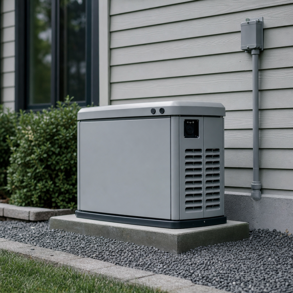
Houston’s residential standby generator installations are governed by the 2018 International Residential Code (IRC) (adopted by Houston with local amendments), NFPA 37, and the 2020 National Electrical Code (NEC), with nuanced plan-review expectations and redlines arising from Houston-specific interpretations and workflows. Detailing generator placements, meeting clearance and enclosure requirements, specifying fuel and electrical service paths, and annotating site plans for review all demand rigor from drafters-especially given frequent city redlines for missing citations, incomplete dimensions, and inadequate utility details. Each stage, from site dimensioning to utility connection and cross-sheet annotation, is a potential choke point for approvals; meticulous adherence to structural, gas, and electrical code-plus local zoning and amendment overlays-is essential.
Detailing Code-Compliant Generator Placement and Clearances on Houston Residential Site Plans (IRC 2018 & NFPA 37)
Code and Zoning References in Houston Plan Sheets
Houston operates under the 2018 IRC with specific city amendments, crucially impacting generator clearance and placement criteria, notably in the R-1, R-2, and R-3 zoning districts. These requirements must be visible on the Site Plan with direct code citations, not only to pass plan review but also to guide future field inspections.
- IRC 2018 Chapter 3: Building Planning, Section R302.1 - Fire-resistance rating of exterior walls affects placement near buildings.
- IRC 2018 Chapter 24: Fuel Gas, Section G2406.2 - Prohibits installation of combustion appliances in particular locations, prohibiting unsafe generator placements.
- Houston Local Amendments - May add further setback or fire-resistance requirements; must check the Houston Permitting Center for latest.
- NFPA 37, Section 4.1.4.1 - Requires minimum 5 feet from generator enclosure to any wall opening and from combustible structures, unless supported by 1-hour fire-rated construction or formal fire propagation analysis.
Plan-Set Dimensioning Practices and Common Redlines
Dimensioning must be explicit, visible in feet and inches, and reference all relevant clearances to:
- Nearest property lines (typically minimum 2 feet, but verify against zoning for R1/R2/R3 lots).
- Adjacent building openings (NFPA 37 minimum of 5'-0" horizontally, measured perpendicular to opening edges).
- Adjacent combustible construction - If under 5', include explicit detail showing one-hour fire-resistive wall type and assembly reference.
Typical site plan code call-out:
“GENERATOR LOCATED MIN. 5'-0" FROM ALL BUILDING OPENINGS AND COMBUSTIBLE EXTERIOR WALLS; SEE NFPA 37 SEC. 4.1.4.1 AND IRC 2018 SEC. R302.1 AS AMENDED BY CITY OF HOUSTON.”
Plan-review redlines often note: “Dimension from generator to nearest building opening missing. Demonstrate compliance with NFPA 37. Add IRC Sec. R302.1 callout for wall construction if under 5’-0”.”
Noise, Zoning, and Special Siting
The Houston Noise Ordinance (Sec. 30-3, City Code) restricts residential noise, especially at property lines. Standard drafters’ note: “GENERATOR COMPLIES WITH HOUSTON NOISE ORDINANCE, NOISE LEVEL AT PROPERTY LINE NOT TO EXCEED 58 DBA PER SEC. 30-3.” Site plans in R-1 and R-2 generally require this, as redlines often flag missing noise compliance annotations.
Zoning districts may limit generator location within required side or rear yards, especially for corner lots (suburban R1, R2). Plan reviewers expect setback dimensions across property lines and cross-ref in the zoning summary table (“GENERATOR SITING PER R1 MIN YARD SETBACK, VERIFY 3'-0" TO PROPERTY LINE”).
Drawing Conventions: Plan, Elevation, and Section
- Site plan: Generator shown by unique symbol (e.g., GEN-1), with leader noting capacity (kW), fuel type, clearance dims to building, openings, and lines.
- Architectural/Structural sheets: Wall sections, if less than 5’ from generator, are keyed with explicit fire rating (1 HR, per UL or ASTM E119 tested assembly) and plan annotation: “SEE DETAIL 6/A4.2 FOR 1-HR FIRE WALL PER IRC 2018 R302.1.”
- Elevations: Generator height relative to grade, position of exhaust, and offset from walls, doors, and windows.
- Access route: Minimum 36" service access, dimensioned and called out: “MIN. 3'-0" MAINTENANCE CLEAR REQUIRED AT FRONT PANEL”.
Architectural and Structural Detailing for Generator Enclosures and Pads in Houston Residential Permitting
Enclosure Materials, Ventilation, and Access Annotation
Stationary generator enclosures, whether factory-certified or site-built, follow NFPA 37 and IRC enclosure principles, with plan sheets expected to:
- Specify non-combustible materials (“ENCLOSURE: 14 GA. GALVANIZED STEEL PANELING, FINISH: POWDER COAT, PER ASTM A653” or equivalent aluminum/stainless steel if applicable).
- Dimension integral or louvered ventilation openings per manufacturer specs (“VENT OPENINGS BOTH ENDS, MIN. 45 IN2 FREE AREA EACH, SEE NFPA 37 4.1.4.2”). Plan reviewers flag undersized or improperly placed vents.
- Show access panels or doors (“ACCESS DOOR, 36" WIDTH MIN FOR SERVICE, LOCKABLE, MAINTAIN 36" CLEAR IN FRONT, SEE NEC 2020 ART. 110.26”).
On the architectural elevation: call out notch for exhaust/vent, doors, and panel numbers keyed to schedules. Standard note: “ENCLOSURE AND PAD TO COMPLY WITH NFPA 37, IRC 2018 CH 24, AND GENERATOR MANUFACTURER’S INSTALL PROPERTY MAINTENANCE MANUAL”.
Pad Section, Reinforcement, and Anchorage
Foundational support is a frequent redline focus point. Common plan annotations and section callouts, as seen on University of Houston’s Engine-Generator Specs:
- Pad dimensions: Minimum 4'-0" x generator length plus 12", width plus 12", thickness 6"; reinforce with #4 rebar, 12" o.c. ea. way.
- “CONC. PAD: 4,000 PSI MIN, 6" THK, W/#4 REBAR @ 12" O.C. EW, CENTERED (3" COVER), PAD EXTENDS 6" BEYOND ENCL. ON ALL SIDES.” If local soils require, show additional footings as dictated by engineering or local code.
- Anchor bolts: “ANCHOR BOLT: 5/8" DIA. ASTM F1554 GR.55, 7" EMBED, LOCATION PER MFG. BASE TEMPLATE, COORD. FINAL W/ GENERATOR SUPPLIER.”
Elevation details must clarify pad height above finished grade and relationship to grade sloping for drainage (“PAD TOP FINISHED 2” ABOVE AVERAGE GRADE, SLOPE AWAY FOR POSITIVE DRAINAGE, TYP”).
Fire Separation and Typical Review Comments
If separation to structure is below 5 feet, plan reviewers require:
- Explicit fire-resistive wall section (“1-HR FIRE RATED WALL, SEE UL DESIGN U305, TO EXTEND FULL ENCL. LENGTH + 1’-0”, FROM SLAB TO UNDERSIDE OF EAVE”).
- Material key schedule, listing fire-rated assemblies and continuous fire seal at penetrations (“PENETRATIONS: F-RATED FOAM OR METAL COLLAR, UL CLASSIFIED, TYP”).
Common redline: “Wall adjacent generator does not indicate fire rating for 1-hour. Provide section and product specifications, per IRC R302.1 and NFPA 37 exception.”
Missing pad detail, lack of reinforcement notation, and ambiguous anchor bolt sizes are routinely cited in “CONCRETE SLAB DETAIL INCOMPLETE-REINFORCEMENT/OFFSET NOT SHOWN. ADD STRUCTURAL SECTION WITH MATERIAL SPEC.” comments.
Integrating Fuel Gas (IRC Chapter 24) and Electrical (NEC 2020) Connections into Houston Generator Permit Drawings
Fuel Gas Piping Design, Notation, and Review Issues
All fuel gas piping design, dimensioning, and call-outs must precisely follow IRC Chapter 24, Houston amendments, and directly cross-reference the generator’s nameplate BTU/h rating in plan-set gas load calculations.
- Load Calculation Table required; sum of all connected gas appliances at maximum operation (
IRC 2018 G2413.2), explicitly including generator BTU draw (“GAS LOAD CALC: GENSET=170,000 BTU/H, FURNACE=80,000 BTU/H, TOTAL = 250,000 BTU/H”). - Method shown: “SIZING BY LONGEST LENGTH PER G2413.4.1, SEE TABLE ATTACHED, PIPE SIZE 1” CSST, MAX RUN = 65’, SERVES LOAD AT 7.0” WC.”
- Piping schedule: “GAS PIPE: 1” SCH 40 STEEL, TYP, PAINTED YELLOW, BURIED 18" MIN., PROTECTED BY SLEEVE AT EMERGENCE.”
- Valve and sediment trap: “BALL SHUTOFF VALVE AND DRIP LEG WITHIN 6’ OF APPLIANCE, PER G2420, G2419.” Shutoff valve and sediment trap must be shown symbolically and dimensioned on plumbing/gas diagram.
Common redline: “Pipe size calculation not included, G2413.4.1 table missing, add generator load to overall calculation to verify adequate fuel pressure for all appliances.”
Electrical Routing, Transfer Switch, and Grounding
Electrical riser and one-line diagrams must present:
- Route from generator to ATS (automatic transfer switch), then to main panel; all connections labeled with conduit size/type (“1” RMC OR PVC SCH 80, BURIED 18” MIN. PER NEC 2020 TBL. 300.5” where exterior or below-grade).
- Disconnect switch: show location within sight of generator (“EXTERIOR RATED NON-FUSED DISCONNECT, MOUNTED ON ENCL. NEAREST CORNER, SEE NEC 445.18”).
- Wiring schedule: “GENERATOR FEED (L1, L2, N, G): 3#6 & 1#8 CU THWN IN 1” PVC, VERIFY LENGTH VS. NEC 310.16 AMPACITY.”
- Grounding: “BOND TO UFER AT PAD OR SEPARATE GROUND ROD, 8’ MIN, #6 CU. TO GROUND LUG, SIZED PER NEC 250.66.”
Transfer switch integration must include cut sheet submittal and symbol key (“AUTO TRANSFER SWITCH (ATS)-MODEL [MANUF], 200A RATED, UL1008 LISTED, RAPID-CLAMP, SEE PANEL SCHEDULE”).
Electrical load calculation table (“LOAD CALC PER NEC 220.82: GENSET SIZED FOR 21.5 KW, TOTAL SELECTED LOADS (REFRIG, HVAC, SUMP, MISC): 19.8 KW”) must be visible in plan set for generator sizing validation.
Common electrical review redlines: “ATS model/type not specified, incomplete riser diagram, missing load calc per NEC 220.82, unclear conduit type at exterior-clarify for plan review.”
Drawing Sheet Conventions-Symbols, Legends, and Coordination
- Electrical sheets: Standardized symbols for generator (GEN), ATS, exterior disconnect, main panel, conduit with arrows indicating routing.
- Legend table: Deciphers all abbreviations, e.g., “GEN=GENERATOR, ATS=AUTOMATIC TRANSFER SWITCH, DP=DISCONNECT PANEL”.
- One-line electrical diagrams and plumbing/gas schematics placed on dedicated sheets and referenced on both site/architectural and specialty MEP sets-plan reviewers expect direct cross-referencing, not separated by discipline.
Standardized Drawing Sheet Mechanics and Annotation for Generator Installations in Houston Permit Sets
Required Sheets, Notes, and Capacity Annotation
Standard Houston residential generator permit packages will minimally include:
- G-001 Cover/General Sheet: Project data, code summary (“ALL WORK TO 2018 IRC W/ CITY OF HOUSTON AMENDMENTS, 2020 NEC, HOUSTON NOISE ORD.”), index, and abbreviations.
- SITE PLAN: “GENERATOR: KOHLER 24KW, AIR COOLED, NATURAL GAS, SEE ELECT. SCHEDULE FOR LOADS.” Dimensions to property lines, structures, and all doors/windows. Cross-reference note: “LOCATION PER NFPA 37 4.1.4.1, MAINTAIN 5'-0" FROM ANY BUILDING OPENING.”
- ARCH SHEETS: Elevations and sections showing enclosure/pad, maintenance clearance (“3'-0" CLEAR AT SERVICE ACCESS FACE, REQ’D PER MFG, NEC 110.26”). Construction details at reduced setbacks: “WALL TYPE A, 1-HR, SEE DETAIL 2/A-401; ASSEMBLY U305, GYP TO STRUCTURE, PER IRC R302.1.”
- ELECT PLANS: Riser and one-line, generator, ATS, panelboard, grounding electrode, conduit routing, disconnect location. Symbol key and note: “ELECTRICAL INSTALLATION PER NEC 2020, ART 445.18, ART 702.”
- PLUMBING/GAS PLAN: Schematic diagram, pipe sizing calculation, shutoff valves, sediment trap (“ALL WORK TO COMPLY W/ IRC CH 24, HOUSTON LOCAL AMENDMENTS, FLEXIBLE GAS CONNECTOR PER MFG”).
Generator capacity and fuel type appear conspicuously in all plan legends: “GENERATOR: 24 KW, 120/240V, 1 PH., FUEL: NG, 230 CFH. MAINTENANCE ACCESS: 36" FRONTAL CLEARANCE MINIMUM.”
Code Reference Callouts and Plan Cross-References
- Typical note: “SEE IRC 2018 SEC. R302.1 FOR WALL FIRE RATING; SEE NFPA 37 4.1.4.1 FOR SETBACKS, SEE NEC 2020 ART 445 & 702 FOR ELECT GENSET WIRING.”
- Explicit sheet cross-refs: From site plan, “SEE DETAIL 1/E-501 FOR ELECTRICAL RISER”; from arch sheet, “SEE SITE PLAN FOR LOCATION, SEE STRUCTURAL DETAIL FOR PAD.”
Common omission redlines include: “Refer to specific code section for clearance; generic ‘per code’ not accepted.” and “Main panel/generator capacity not listed-clarify on legend for review.”
Symbols, Dimensions, and Material Schedules
- Symbols are customarily included with text labels, e.g., “GEN” for generator, “ATS” for transfer switch, “DP” for disconnect panel. All electrical/plumbing icons to be defined in legend, not just on-line.
- All clearances and access pathways are accurately dimensioned (“5'-0" TYP MIN. TO GLZ’D OPENINGS”; “3'-0" MAINTENANCE CLEAR FRONT PANEL”); plan reviewers cite “clearance dimensions missing/inconsistent site vs. elevation sheets.”
- Pad thickness, anchor bolt sizes, and reinforcement are listed in a dedicated material “generator pad/foundation” schedule: “4,000 PSI CONC, #4 REBAR 12" O.C. EW, 5/8" DIA. ANCHOR BOLTS 7" EMBED.”
Anticipating and Addressing Common Houston Permit Review Redlines for Residential Generator Submissions
Frequent Plan Review Redlines and Their Underlying Triggers
Nearly every Houston generator permit review includes comments for:
- Missing or incorrect code citations: Plan reviewers habitually note, “Provide IRC 2018 Section R303.4 for ventilation,” if mechanical or enclosure venting details lack the direct cross-reference.
- Inadequate dimensioning: “Provide dimensions from generator to property lines, building, and adjacent glazed openings to verify clearance compliance per NFPA 37.”
- Utility connection omission: “Include gas line size calculation and routing. Label all gas/electric shutoff and disconnects. Show all connections and utility details.”
- Sheet coordination lapses: “Site plan and electrical plans conflict in generator location-revise for consistency.”
- Incorrect enclosure/pad spec or lack of fire-rated detail: “Pad section missing rebar schedule; wall adjacent generator lacks required 1-hour fire rating-detail not provided. See IRC R302.1.”
Best Practices for Drawing Annotations and Plan Coordination
- Direct code reference on every detail: All critical details need an explicit reference (“SEE NFPA 37 4.1.4.1 FOR 5’ MIN CLEARAN.”; “SEE IRC R302.1 FOR FIRE WALL RATING”).
- Plan-wide utility connection integration: Fuel gas diagrams must list BTUs, pipe size, run length, and terminus at generator base; electrical one-line shows conduit size, wire gauge, disconnect, transfer switch, and panel reference numbers. Annotations and load/gas calculations appear in the plan, not just in specs.
- Pad, wall, and material sections are included on the architectural or structural sheets, labeled DETAIL numbers referenced from the site plan (“SEE DETAIL 2/S-201 FOR PAD AND ANCHORAGE”).
- Coordination across all sheets: Ensure generator symbol, size, and position are consistent; cross-sheet references to details and schedules prevent conflicting dimensions or duplicate work-most redlines are a result of basic inconsistency between site, arch, MEP sheets.
Specific Dimensions, Ratings, and Manufacturer Compliance
- Setbacks: 5’-0” horizontal from all wall/roof openings and combustibles unless fire-rated wall detail provided; minimum 2’-0” to property line or per stricter R1/R2 zoning minimum, whicever is greater.
- Pad: 6” concrete slab, 4,000 psi, 12” offset from enclosure, rebar grid 12” o.c. e.w., 5/8” anchor bolts, exposed pads finished 2” above grade.
- Fuel gas line: Pipe sized to generator + all other appliances, using IRC G2413.4.1, labeled length and BTU; buried 18" min. unless otherwise required by HOU amendments.
- Electrical: ATS location within sight of generator, shown on plan. Disconnect switch required. Conductors and conduit sized and noted on plan per NEC 310.16 and installer recommendation.
References for City-Preferred Workflow and Documentation
- Houston Permitting Center - Generator Permit Requirements
- IRC 2018, Chapter 24 - Fuel Gas
- 2020 NEC
- Houston Code Development and Local Amendments
- UH Master Spec for Engine Generators
Coordinated, code-cited, and dimensionally complete generator plan sets-integrating all mechanical, utility, enclosure, and structural details-are endorsed by Houston reviewers and meet the city’s rigorous redline standards. For precise, permit-ready drafting serving developers and builders across Texas, Kingsway Drafting & Design sets the benchmark in code-integrated architectural plans.