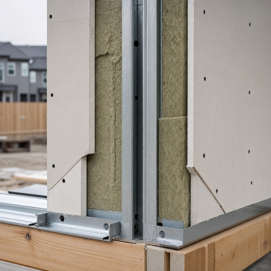
Code-compliant fire separation in attached townhouses within Houston, TX, hinges on rigorous detail, precise dimensioning, explicit code referencing, and a nuanced understanding of both national codes and Houston-specific amendments. Every phase from plan sheets to jobsite inspections-and every discipline from architectural to mechanical-must coordinate to maintain the continuity and integrity of 2-hour fire-resistance-rated assemblies mandated by Houston’s adopted 2018 IRC and the city’s amendments. The following technical analysis details how plan-set documentation, code call-outs, and assembly details secure jurisdictional approval and constructability for fire-separated townhouses in Houston.
Detailing 2-Hour Fire-Resistance-Rated Common Wall Assemblies: Sheet Sections, Interfaces, and Framing in Houston
Houston’s adoption of the 2018 International Residential Code (IRC), with specific amendments, sets the standard for fire separation between attached townhouse units. Section R302.2 states:
- “Each townhouse shall be separated by a minimum 2-hour fire-resistance-rated wall assembly if a fire sprinkler system in accordance with Section P2904 is not installed.” (2018 IRC R302.2)
Review of local amendments must occur at project outset, as minor updates or enforcement interpretations by Houston’s Building Code Enforcement may change project submittal requirements annually. Houston’s interpretations of this code are readily available through the Houston Permitting Center website.
Common Wall Assembly: Drawing Conventions and Code Call-Outs
In Houston, the assembly is drawn in full section from the slab-on-grade foundation to the roof sheathing or deck, referencing tested assemblies (typically UL or ASTM E119). Plan reviewers commonly redline any absence of:
- Explicit system reference and wall schedule
- Plan, section, and detail call-outs for typical and unique conditions
- Assembly continuity at head, sills, and floor-line transitions
- STC (Sound Transmission Class) notation for acoustic compliance between units Code reference annotation-e.g., “2-HR FIRE-RATED SEPARATION WALL, PER 2018 IRC R302.2, UL DESIGN U334, 50 STC MINIMUM” at each relevant sheet location
Houston’s plan review comments frequently cite missing or insufficient continuity details. A standard redline example: “Revise Sections A/A2.1 and B/A2.2 to detail fire barrier at head, sill, and foundation per UL assembly approved for 2-hour rating. Provide full-depth dimension from slab to roof deck.”
Head/Sill, Floor/Foundation, and Framing Integration
Every wall section crossing a horizontal plane-slab edge, first and second floor decks, roof-must show a detailed assembly break, not simply a “typical” note:
- Head Condition: 2 layers of 5/8" Type X GWB (gypsum wall board), carried uninterrupted behind structure to underside of roof sheathing, maintained around trusses/rafters with fire caulk or mineral wool. Double top plates offset or continuous for structural and fire separation.
- Sill/Base Condition: Slab edge receives direct application of rated boards, caulked at concrete interface with listed fire sealant. Call out physical dimension-e.g., “2 layers 5/8” Type X GWB commence 3-1/2" above finished slab.”
- Intersecting Floors: If wood joists or trusses, fire-resistance must wrap around penetrations at floor framing; illustrate in detail reference-e.g., “Detail 2/A3.1: Fire-rated boxing with mineral wool and 2 layers Type X GWB around all penetrations.”
Houston’s preference for double-stud assemblies is both for fire and acoustic performance. Plan reviewers may redline single-stud party walls with a note: “Recommend double-stud or shaftwall party wall for STC compliance between units: verify UL/GA assembly provides both 2-hr and 50 STC minimum per city guidance.”
Material, Assembly, and Dimensioning Standards
Typical details as accepted in Houston’s plan review include:
- Primary Structure: 2x4 wood studs (double offset) at 16" o.c., or 2x6 staggered; cavity filled with mineral wool batt; double top plate each side, offset base plates.
- Sheathing: 2 layers of 5/8" Type X GWB each side, full height from slab to roof deck; reference UL assembly on all elevations and in wall schedule.
- Vertical continuity: Dimension from finish floor/slab (“0’-0” FF”) to bottom of rafter/roof deck (“+19’-2” typical 2-story”), with GWB and mineral wool notes extending continuously.
- Sealant: Fire-rated intumescent sealant at all junctions (slab interface, roof deck, window/door penetrations), labeled: “LISTED FIRE-RATED CAULK, 3/8" continuous bead (UL SYSTEM W-L-1234 or EJS1234, typ.)”
- Test Evidence: UL design number/GA file or ESR reference included on both plan and detail sheets.
Omission of any referenced assembly, code section, or product specification is routinely redlined. For instance, “Provide 2-hour rated assembly reference (UL or GA FN) with minimum 2x4 double staggered studs, 2 layers GWB both sides, mineral wool insulation. Identify STC >50. Revise Note S-3/A6.2.”
Firestopping and Penetration Detailing for Wall Services: UL Systems, Code, and Sheet Conventions
Maintaining the tested ratings across all MEP penetrations is paramount. IBC Section 714, as adopted (and amended) by Houston, sets standards for penetration protection.
UL-Rated Systems and Firestop Schedules
Drawings must reference a tested assembly and UL System for every rated-assembly penetration. Most Houston plan checkers expect:
- Keyed callouts for each system-e.g., “PIPE PENETRATION, SEE DETAIL 14/A6.2, UL SYSTEM W-L-1234, 2 HR.”
- Penetration schedule or table: trade, wall location, penetration size/type, UL system reference.
- Redlines if schedules state only “fire caulk @ all MEP penetrations”; require explicit listed system, size, substrate, and allowable annular space.
Electrical boxes require special documentation under IBC 714.4.2, which Houston plan review often flags in redlines:
- Box size: Maximum 16 in² individual, aggregate 100 in² per 100 ft² of wall area, per membrane face.
- Spacing: 24" minimum between boxes opposite sides unless using listed putty pads (e.g., SpecSeal, 3M, referenced via UL classification).
- Note example: “ALL ELECTRICAL BOXES IN 2-HR PARTY WALL: SIZE & SPACING PER IBC 714.4.2. Putty pads (UL WJFO) if separation <24” O.C.”
Material Specs, Dimensions, and Code Detailing
Wall assembly sheets must detail:
- Penetrating item: Material (e.g., “1" copper supply,” “2" PVC DWV”) with rough-in dimension referenced to baseline grid and elevation so trade coordination is clear.
- Firestop method: “UL System W-L-1234, 5/8" mineral wool batt pre-packed, 3/8" intumescent sealant both sides of wall.”
“Penetration firestop detail: 2” annular space MAX, fill as tested. Insulation: Fire-rated mineral wool, 4 PCF min. density.” - Fireblocking for plumbing/HVAC: “All vertical/horizontal pipe chases fireblocked at 10' intervals, at floor/roof transitions, with 2" nominal wood firestop or approved mineral wool per R302.11.”
Omissions in MEP coordination or “missing firestop details for rated assemblies” are pervasive in both plan review and on jobsite punchlists; referencing the UL system directly in callouts is mandatory for approval in Houston.
Continuity of Fire Separation at Roof-to-Wall and Exterior Junctures: Parapet Heights, Fireblocking, and Property Lines
Controlling fire spread at building perimeters is a core focus of Houston’s plan review and inspections, especially at townhouse ends and parapet transitions.
Parapet and Roof/Wall Interface Detailing
Assemblies abutting the roof must illustrate fire-resistance continuity per IBC 705.11.1 and Houston’s local code:
- Minimum parapet height: 30" above roof, full width of party wall, drawn in both section and roof plan with dimension tick/label “30” MIN ABOVE ROOF DECK; NONCOMBUSTIBLE COPING AND GWB BOTH SIDES.”
- Fire barrier continuity: “2-HR UL X#XXX CARRIER WALL CONTINUOUS FROM FOUNDATION TO UNDERSIDE OF ROOF SHEATHING. GWB CAPPED TO PARAPET; RIGID INSULATION MINERAL WOOL TO UNDERSIDE OF SHEATHING.”
This is a frequent comment in plan review: “Revise Sheet A4.1. Parapet must project a minimum 30 inches above adj. roof surface. Show UL assembly through parapet; coping and flashings to be noncombustible.”
Fireblocking at Soffits and Attics: Sheet Notation and Detail
Fireblocking to control hidden fire paths must extend across all concealed transitions per IRC R302.11 and Houston’s amendments. Every floor plan, reflected ceiling plan, and wall section must show:
- “FIREBLOCKING: 2” NOMINAL LUMBER OR MINERAL WOOL (4 PCF), AT CHANGE OF DIRECTION, SOFFIT BEARING, AND EVERY FLOOR/ATTIC INTERFACE.”
- In detail: highlighted hatching, dimensioned call-out parallel to joist direction; “FIREBLOCK @ MAX. 10' O.C., SEE 3/A5.2.”
- Mechanical or appliance chases: “Chase wrapped with (2) layers 5/8” Type X GWB from conditioned space into attic, top sealed w/ mineral wool, fire-rated sealant.”
Redlines requiring additional clarification are routine: “Detail roof soffit/party wall interface at attic. Indicate type and location of fireblocking at concealed tee-joins.”
Property Line Wall and Projection Detailing
IRC R302.1 specifies critical dimensions and restrictions for end units and exterior walls:
- 1-hour rating required when wall <5’ from property line, assembly tested both sides.
- No projections within 2’ of line; between 2’ and 5’, undersides must have 1-hour rating.
- No windows or doors when wall <3’ from property line.
Construction documents must reflect these stipulations graphically:
- Wall assembly tag: “1-HR FIRE-RATED EXTERIOR WALL PER IRC R302.1(2), 5/8” TYPE X GWB BOTH SIDES, GYPSUM SHEATHING OUTBOARD OF STUDS, ACCEPTED UL DESIGN #.”
- Dimension annotation: “2’-0” MIN PROPERTY LINE OFFSET, TYP.” “No proj. within 2’, ref. Section/Elevation 4/A7.3.”
- Section cut referencing missing exterior fenestration: “NO OPENINGS; SEE EXTERIOR WALL R302.1 REQ.” for redline mitigation.
Integrating Houston-Specific Amendments and Plan Submission Protocols: Notes, References, and Sheet Mapping
Houston’s enforcement of the 2018 IRC/IBC is defined heavily by local amendments, available through the Houston Permitting Center and Houston Fire Department. These amendments are routinely cited in permit reviews.
Code Section Referencing in Drawing Notes
Every rated assembly in a Houston submittal should be annotated with the relevant base code and, where applicable, Houston’s amendment. Examples of explicit note protocols:
- “2-HR FIRE-RATED PARTY WALL PER 2018 IRC R302.2; CONSTRUCT PER UL DESIGN U334; SEE HOUSTON AMENDMENT TO R302.2.2. INCLUDE SOUND ATTENUATION AS NOTED, 50 STC MIN.”
- “CONTINUOUS FIREBLOCKING PER 2018 IRC R302.11 AND HOUSTON LOCAL AMENDMENT SEC. 302.11.1-CONCEALED SPACES, DRAFTSTOP 10’ O.C. MAX.”
Referencing both the national section and Houston-specific amendment is a non-negotiable for first-round approval.
Mapping Requirements to Plan-Set Sheets
Technical review in Houston expects that required notes and details are mapped to the correct plan sheet:
- Site Plan: Location and width (“8” TYP.”) of party wall relative to lot line (“PARTY WALL 0’ O.C. TO LOT LINE; 2-HR RATED, SEE A6.1”); fire lane compliance (“Fire apparatus access: 20’ MIN CLEAR, RADIUS 28’ MIN, HOUSTON FIRE CODE 503.2.4”).
- Floor/Roof Plan: Wall assembly tags for each wall/shaft/fire separation, coordinated with wall schedule and sheet reference. Example: “W1 = 2-HR PARTY WALL, SEE SECT. 1/A4.3.”
- Wall Sections/Details: Complete, continuous section reference, fire-resistance schedule table, U/L design number, and note: “ASSEMBLY CONTINUOUS, SEE DETAIL AT SLAB-ON-GRADE AND ROOF (4/A6.4, 5/A7.1).”
- MEP Coordination Sheets: Penetration schedule: “All penetrations through rated assembly to comply with UL SYSTEM W-L-XXXX, COORDINATED WITH ARCH SHEET A10.1.”
Lack of mapping between note, section, detail, and assembly number is frequently a basis for “Plans incomplete: mapping of code-required fire-resistive elements unclear, see markups.”
Fire Life Safety: Submission Format and Material Requirements
Houston’s permit department requires a clear fire/life safety summary, including page index and separate fire separation plan if project exceeds three units or includes multistory massing. Plan reviewers expect:
- Submittal checklist: “Fire-rated wall schedule, UL design references, code section notes mapped to plan.”
- Material specs: “Type X GWB, 5/8”, 2 layers, both sides party wall”; “Firestopping: Hilti FS-ONE or 3M CP25WB+, UL system compliance, fire/life safety submittal sheet refs.”
- Inspection notes: “Fire/Smoke barrier assembly to remain exposed for city inspection prior to closure. Contractor to verify wall configuration, stud spacing, insulation, and board fastening at designated location (callout: SEE SHT A5.6, ELEV. 2A)”
- Plan redline trigger: “Assemblies not identified by U/L, GA, or ASTM E119 listing; resubmit with assembly reference, not manufacturer spec alone.”
- Submission format: Digital PDF with layers, readable callouts, color-coded indexes for fire/life safety features preferred; poor sheet legibility or imprecise annotation results in round-tripping with “Revise sheet X: fire/life safety plan not clear; resubmit per city format.”
Dimensioning for Constructability: Structural Offsets, Slab-on-Grade, and Framing Coordination in Houston
Houston’s architectural drafters must integrate not just code and assembly references, but structural and constructability details critical for jobsite success and inspection approval. The city’s townhouse market is dominated by slab-on-grade construction and tight unit adjacency, presenting recurring challenges for continuity and coordination.
Integration of Structural Offsets, Framing Coordination, and Assembly Continuity
Under IRC R302.2.3, “Fire-resistance-rated walls separating townhouse units shall be continuous from the foundation to the underside of the roof sheathing, deck, or slab”-which is rigorously enforced in Houston. Key drafting details to ensure constructability include:
- Offset at Foundation: If slab-on-grade foundations stagger or step (e.g., “WITH 8” CMU STEMWALL STEP, DETAIL 7/A8.2”), detail both wall and fire-resistive continuity-draw GWB layers, insulation, fire caulk around corner/step, and breaklines with explicit dimensions shown to bottom of GWB/CMU interface.
- Tie-in at Floor Framing: Detail party wall as continuous up past floor framing. “ALL FLOOR JOISTS BEAR BOTH SIDES OF PARTY WALL; NO PENETRATION OF CONTINUOUS GWB. IF ENGINEERED TRUSS, FLASHING PATCH AND 2-HR RATED WRAP AROUND BEARING, EXTEND GWB WITH OVERRIDE FLANGE, SEE 4/A9.1.”
- Joist Framing/Vertical Alignment: Any vertical misalignments or “Z” stepbacks in the units must show continuous GWB and mineral wool, not assumed “typical” framing. Example detail label: “SEE OFFSET PARTY WALL SECTION 3/A8.4; GWB EXTENDS FULL WIDTH ACROSS PLAN OFFSET.”
- Masonry/CMU Integration: For townhouse facades using brick veneer or CMU at property lines, “1-HR BLOCK WALL EXTERIOR, 2-HR GWB INSIDE FACE, DIMENSIONED 3-5/8” GWB OFFSET FROM BRICK LINE, PER R302.1 & CITY AMEND.”
Structural elements (beams, columns, bearing ledgers) must not compromise the party wall. Redline example: “No wood girder bearings inside fire-rated separation. Shift support per ‘Detail 11/A7.2’ or use noncombustible supports.”
Plan Notes for RFIs and Jobsite QA
Many jobsite RFIs in Houston relate to unclear dimensioning or breaks in fire protection continuity. To mitigate:
- Clear section marks at all changes: “2-hr party wall, continuous; step in foundation shown at B/A4.5, dimension all changes and fireproofing at offset.”
- Noted inspection points: “Contractor to coordinate inspection of fire wall prior to GWB closure. Provide unimpeded site view from slab to roof at mid-wall.”
- Detail-specific coordination notes: “No cavity bridging/blocking permitted in party wall between units except as detailed, see fireblocking SEC 5/A9.3.”
- Explicit trade separation: “MEP trades: no cutting of double-stud assembly at base plate. Penetrations per UL schedule only (see A10.2).”
- Slab reveal dimension: “Minimum 4” GWB bottom clear to finished Slab Elev. per Detail 9/A7.3, account for slab slope and tolerance plus firestop sealant.”
Omission of continuity drawings or dimension chains is a near-universal source of permit or inspection delays. Houston reviewers habitually redline: “Show all vertical offsets, dimension slab stepdowns, confirm GWB continuation and fireblocking at transitions in plan and section.”
Material Specs, Codes, and Dimension Standards for Houston
- Party wall thickness: 7" minimum (double 2x4 wall plus 2x Type X GWB both sides, 1” air gap typical); all dimensions shown layer by layer in detail.
- Fire-resistance rating: 2 hours if not sprinklered, 1 hour with IRC-compliant sprinklers. Annotate: “2-HR U334 ASSEMBLY; 50 STC MIN REQUIRED.”
- Continuity from slab to roof: Assembly drawn as single hash-mark section uninterrupted; all steps/level changes called out and dimensioned to scale (callout: “SEE SHEET A7.2 FOR SLAB STEPS/SLOPES/TRANSITIONS”).
- No projections/encroachments: “No MEP or framing protrusions through party wall between units unless per listed penetration detail A10.2.”
Conclusion
Code-compliant attached townhouse drafting in Houston demands that every fire separation be detailed in section, mapped to tested assemblies, and annotated per both the 2018 IRC and Houston’s amendments. From parapet to foundation, every interface, service penetration, offset, and finish transition must be explicitly dimensioned and coordinated in cross-discipline plan sets. Material schedules, wall tags, and fire/life safety notes must thread throughout the sheets, with UL designs and code section references always present. In Houston’s intensive permitting environment, well-documented and constructible fire wall detailing is the only path to swift approval and lasting performance.
Kingsway Drafting & Design delivers code-ready, permit-winning fire separation drawings for townhouse projects throughout the United States.