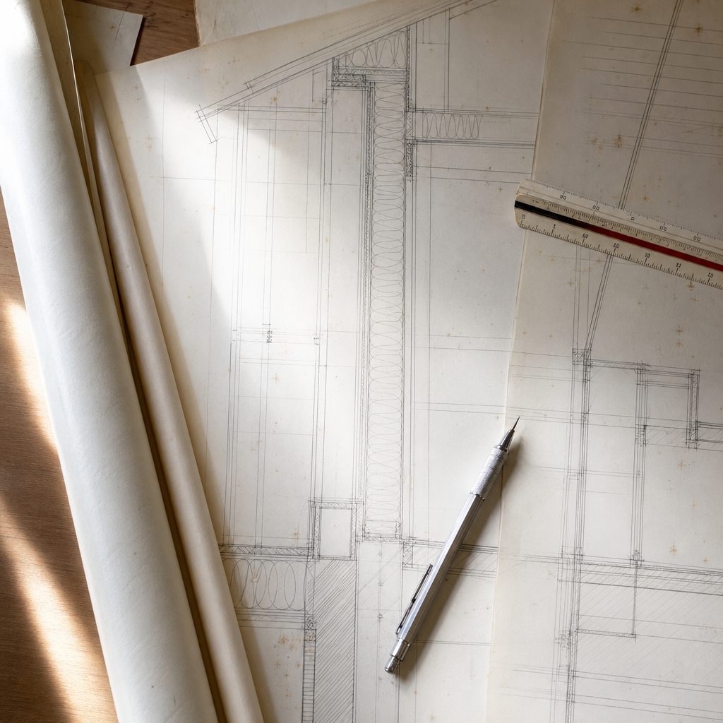
Continuous insulation (CI) implementation in residential construction for Tampa, FL is governed by the Florida Building Code, Energy Conservation (8th Edition, 2023), with specific assembly, dimensioning, and drawing-sheet protocols vital for energy compliance and permit approval.
Code-Driven Requirements for Continuous Insulation in Tampa, FL
Florida Building Code, Energy Conservation (2023 8th Ed.)
Tampa, FL enforces the 8th Edition of the Florida Building Code, Energy Conservation (FBC-EC), which references both International Energy Conservation Code principles and state-specific amendments. All residential permit plans must demonstrate explicit compliance with these sections:
- Table R402.1.2 (FBC-EC): Lists minimum insulation R-values per climate zone and assembly.
- Section R402.2.2 (FBC-EC): Details prescriptive insulation for mass walls (typical in Florida CMU construction).
Tampa, located in Climate Zone 2, must satisfy these minimum prescriptive criteria:
- Mass Walls (e.g., 8" CMU): Either R-4 “ci” (continuous insulation, exterior) or R-6 total, with more than half permitted on interior side. [FBC-EC Table R402.1.2]
- Frame Walls: R-13 cavity insulation or R-4 “ci” exterior may be used, per same table, though less typical in Tampa masonry builds.
Dimensioning Requirements and Assembly Clarity
To address these code points, drawings must:
- Identify the wall assembly substrate (e.g., CMU, poured concrete, frame wall).
- Illustrate the placement, thickness, and continuity of the CI layer in all applicable envelope sections.
- Label CI by manufacturer, material type, thickness, and R-value directly at each cross-section or detail.
Most review rejections in Tampa cite missing or unclear CI dimensioning, insufficient R-value specification, or ambiguous CI placement (especially around fenestrations or transitions).
Local Amendments and Zoning Interaction
While Tampa adopts the statewide FBC and does not deviate from the prescribed CI values, Construction Services Division (CSD) reviewers may request clarification specific to CMU mass wall assemblies and their interface with stucco, brick, or stone veneer, referencing the Tampa CSD Handbook.
In RS-75, RS-60, and RS-50 zoning districts-the most common single-family districts-the FBC-EC applies identically. Only in context with historic overlays or flood-hazard requirements might additional notes be needed.
Plan Sheet Representation of Continuous Insulation
Wall Sections and Assembly Legends
Standard permit plan sheets in Tampa display wall construction through large-scale wall sections and coordinated assembly legends. CI must be represented uniquely:
- Use a distinct hatch or shading pattern for CI, with legend annotation (e.g., “2" Polyiso R-13 ci”) matching the assembly detail.
- On section drawings, CI is drawn as a continuous layer bridging over slab edges, rim joists, wall framing, and around penetrations, explicitly “no thermal bridging except at fasteners” as redlined by most Tampa plan reviewers.
- Include enlarged details (1 ½" = 1'-0", or similar) for typical penetrations and transitions-especially at window/door heads and jambs, roof-to-wall, and foundation wall junctions-referenced from main sections (“See Detail 3/A4.2”).
Sample call-out (on plan or detail):
- "2" Polyisocyanurate Board (Min. R-4 ci) Installed Exterior to CMU, Fully Taped/Sealed at Joints. Continuous Over Slab Edge. Complies w/ FBC-EC Table R402.1.2 for Climate Zone 2."
CI Call-Outs in Structural vs. Architectural Sets
Coordination between architectural and structural plans is flagged often in Tampa plan review. Drafters must:
- Synchronize R-value and CI thickness between architectural sections and structural wall schedules.
- Call out only code-compliant CI after slab pour or tie beam elevation (not interrupted at bond beams or window headers).
- Reference installation notes: “Architectural insulation layer not shown in structural wall section; install per architectural details and FBC-EC Table R402.1.2.”
Material Tagging, R-Value Labeling, and Notation Best Practices
For Tampa permit sets:
- Material tags on plans include manufacturer and product line if predefined (e.g., “Dow XPS Rigid Insulation, 1” = R-5 per ASTM C578”).
- R-values are listed on drawing call-outs, in wall legends, and in the general notes. Product datasheets may be required with submittal.
- Add note referencing compliance: “Provide continuous insulation (CI) per FBC-EC, R402.2.2. All R-values minimum as scheduled. Gaps >1/8” sealed w/ foam. Joints staggered; no exposed fasteners unless per manufacturer system approval.”
Redlines, Permit Workflow, and Typical Plan Review Comments in Tampa
How Energy Code “Redlines” Appear in Review
The City of Tampa’s CSD reviewers reference the FBC-EC and issue redlines targeting clarity, specificity, and code adherence. Common comments and responses include:
- Redline: “Wall assembly at West Elevation does not indicate specific type, thickness, and R-value of CI. Revise to call out CI material throughout.”
- Required Drawing Response: Add labeled hatch on affected wall, tag as “R-4 CI Polyiso Board, 1” thick, Ext. to CMU Block”, referencing energy code table. Provide spec sheet if necessary.
- Redline: “Continuous insulation not detailed at balcony slab edge and parapet wall. Provide section detail showing CI continuity.”
- Response: Show slab edge detail with unbroken CI layer extending up and over slab, around parapet CMU, with note “all edges sealed, insulation continuous per FBC-EC Table R402.1.2.”
- Redline: “Missing energy note: Specify compliance with FBC-EC R402.2 for all envelope elements.”
In volume homebuilder plan reviews, reviewers may also request CI representation in all envelope sections with “unique wall conditions” (stairwells, attached garages, bay windows).
Permit Workflow in Tampa: Submittal, Review, and Corrections
The Tampa Construction Services Division requires digital residential permit submittals (via Accela). Drawing sets must include:
- Floor plans, showing all envelope-facing wall lines and referencing wall sections/assemblies.
- Wall section sheets-typically A4.1, A4.2-where continuous insulation layers are dimensioned and tagged.
- Assembly legend, listing all wall/roof assemblies with CI thickness, material, and total R-value.
- General notes page, listing FBC Energy Conservation compliance statement, and cross-referencing energy calculations.
Permit review typically cycles through initial review, correction round(s) for redlines, and approval upon full code compliance. Expedite approval by making CI details explicit and by including manufacturer installation datasheets with the initial submittal whenever possible.
Energy Calculations and Envelope Assemblies
For compliance with FBC-EC Table R402.1.2, the energy calculations (performed using EnergyGauge or another approved software) must match the wall assemblies shown on plans. Mismatches between calculation inputs and drawn CI location/thickness will trigger correction cycles at CSD.
Best practice is to annotate each wall assembly on the plans with a clear call-out: “Energy calcs reference Wall Type ‘A’ - CMU + 1" polyiso (R-6.1 ci), furring, GWB.”
Drafting Details for Typical Continuous Insulation Conditions in Florida Masonry
Slab-to-Wall Transitions and Thermal Bridging
The critical detailing challenge in Tampa’s construction is maintaining unbroken CI at the slab edge, particularly with stem walls and monolithic slabs. Plan reviewers frequently reject details that show CI terminating above the slab, exposing the “thermal short circuit” at the block-to-slab interface.
- Section drawings must dimension CI wrapping continuously over the slab edge insulation area (shown as minimum 1"-2" thickness, depending on selected material, matching R-4 or greater).
- Any gap between CI at wall and slab is called out to be “sealed with closed-cell spray foam, per manufacturer’s instructions.”
Sample drawing note:
“Extend R-4 continuous insulation 2" min. below finish floor slab; return CI up inside/outside face of stem wall as required for continuous thermal barrier.”
Fenestration and Penetration CI Details
FBC-EC expects that CI remains unbroken at all wall penetrations. Tampa plan reviewers closely examine window and door head/jamb/sill details for:
- CI returning into jamb returns (not pinched or deleted at rough opening).
- Shimming/flashing details that preserve CI continuity, or an explicit note calling out insulation sprintfilling or low-expansion foam at any interruptions (e.g., “Fill voids at window and door frames with low-expansion closed-cell foam. Maintain CI continuity at heads, sills, and jambs.”).
Roof-to-Wall and Floor-to-Wall Junctions
Florida’s precipitation and wind-driven rain events dictate special attention to vapor barrier continuity and water management as CI is installed at roof-to-wall transitions-especially in flat roof assemblies or parapet details common in Tampa infill projects.
- CI shown running up to underside of roof sheathing or slab, lapping behind any WRB or roof membrane, and returning over tie beams as required.
- Section tags reference TPO roofing manufacturer’s detail if CI integrates with warranted roof system.
- Detail call-outs such as “Lap wall CI 2" min. under roof membrane. Tape/seal at all transitions.”
Specifying Materials and Installation for Code-Approved Continuous Insulation
CI Product Selection and Minimum Dimensions
FBC-EC does not stipulate product brand but mandates:
- CI product must meet ASTM standards for intended application: e.g., Polyisocyanurate per ASTM C1289, XPS per ASTM C578.
- Minimum thermal performance: R-4 for exterior CI in Climate Zone 2-commonly achieved by ¾" to 1" XPS (R-5/inch) or 1" polyiso (R-6/inch). Always base drawing call-out on actual tested R-value of the specified product, not nominal insulation marketing.
Drawing note example:
“Provide 1" Polyisocyanurate Insulation Board, Min. R-6 (Atlas EnergyShield or equal), installed continuous per manufacturer’s and FBC-EC Table R402.1.2.”
CI Fastening, Taping, and Sealing
Permit reviewers require clarity on both mechanical fastening (corrosion-resistant furring screws through CI to CMU) and on air/vapor sealing:
- Details should annotate fastener spacing (“6" oc perimeter, 12" oc in field”) and call out a compatible, code-approved tape at board joints (e.g., “Tape CI board joints with manufacturer-specified foil tape, fully sealed and lapped per installation guide.”).
- All penetrations (pipes, anchors, electrical boxes) require annotation: “Seal all CI penetrations with low-expansion foam and flashing tape per insulation manufacturer’s recommendations.”
It is standard to add a general note stating compliance: “CI to provide continuous air and thermal barrier. All seams, fasteners, and penetrations sealed to maintain code-required integrity.”
Material Substitutions and Deferred Submittals
Substitutions for CI material or thickness must be called out as “deferred submittal subject to City of Tampa CSD approval,” and energy calcs updated to suit. If “ci” is used via insulated stucco systems or other assemblies, the exact ICC-ESR or FBC Product Approval Number is typically requested on the plans (e.g., “R-4 ci via FBC Product Approval #FL12345, Stuccomax EIFS”).
Comprehensive Drawing-Sheet Conventions for CI Assembly Documentation
Hatching, Annotation, and Assembly Schedules
The use of distinct hatch patterns (diagonal lines, closed diamonds, crosshatch with bold outline) for CI distinguishes it from batt insulation, sheathing, or air barriers. Each hatch is keyed to an assembly schedule table, appearing on the same sheet as wall sections:
- Entry for each envelope assembly: “Wall Type A: 8" CMU + 1" R-6 Polyiso (ci) + 7/8" Portland Cement Stucco + Interior 1x Furring + ½" GWB.”
- Schedule includes CSI MasterFormat section division (07 21 00 for thermal insulation) and notes approved manufacturers.
CI “Plan Checklists” as Submission Attachments
Tampa’s CSD increasingly requests a plan checklist confirming:
- “Each exterior wall and envelope section details CI thickness, R-value, and product type.”
- “Assembly schedule matches energy calculation envelope input screen.”
- “Details provided for all typical and atypical conditions.”
To minimize corrections’ rounds, attach the completed checklist with the plan PDF during initial submission.
Job-Site Impacts: Inspectors and Field Compliance with Drawn CI Details
Insulation Inspection Stages in Tampa
Field inspection of CI installation is mandated after “dry-in” and before any wall coverings are installed. Tampa building inspectors are provided a copy of the approved permitted set, and review:
- CI material matches specified product (manufacturer, R-value, thickness).
- Installation pattern (joints staggered per plan sections, taped, and sealed).
- Continuity at all transitions: slab edge, around fenestration, roof-to-wall, and between projected walls.
Failure in the field to provide CI per drawn details and FBC-EC leads to “failed” inspection, red tag, and re-inspection fees. If a substitution is made on site, most inspectors require presentation of revised energy calculations and an updated plan/approval stamp from CSD.
Maintaining “Thermal Envelope Integrity” on Site
The most commonly missed item: CI at small pop-outs, cantilevers, and attached garages. Drawings must reflect CI intent; field execution must follow, or updated “as-builts”/revision submittals become mandatory before final CO.
- Typical inspector’s note: “CI interrupted at garage wall-to-conditioned space transition. Revise or repair for envelope continuity.”
Reviewed plans often serve as the checklist for field verification, so drawing clarity and code referencing directly affect job-site approval outcomes.
Putting It All Together: Energy Compliance through Clear CI Detailing
Drafting continuous insulation details for FBC-EC compliance in Tampa means more than just listing an R-value on a legend. Every exterior envelope section must be meticulously drawn to show CI thickness, material, placement, and continuity-annotated and hatched distinctly per local standards. Energy calculations must be referenced on plan and match the field assembly, and all manufacturer instructions referenced or attached per City of Tampa requirements. Drawing clarity at the transition points-slab edge, openings, roof juncture-prevents common plan review redlines and field compliance headaches. Attention to code language (“R-4 ci”, “per FBC-EC Table R402.1.2”) and city checklists ensures that the permit process flows without unneeded iterations and the constructed building delivers the intended performance, verified at inspection.
All these practices reflect Kingsway Drafting & Design’s commitment to precision, code compliance, and client success in Florida residential construction.