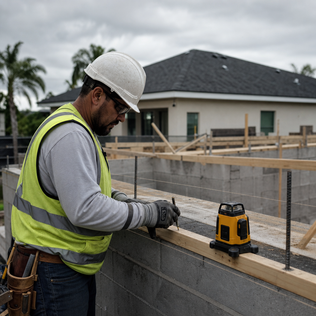
The 2023 Florida Building Code (Residential), as adopted by the City of Orlando, establishes some of the most stringent high-wind requirements in the United States for concrete masonry (CMU) residential construction. Wind speeds in Orlando’s urban and surrounding zoning districts call for a rigorously detailed, dimensioned, and clearly specified continuous load path on architectural and structural plan sets-a vital necessity to pass local plan review and ensure life safety.
Foundation-to-CMU Wall Anchorage Detailing for High-Wind in Orlando
Anchor Bolt Schedules, Spacing, and Embedment: Sheet-Level Details
Effective transfer of roof and wall uplift loads begins at the foundation-to-wall interface. A continuous load path by necessity starts with robust anchorage between the concrete foundation and the base of the CMU wall. Under FBC 2023 Section R403.1.6, all exterior walls require 1/2-inch diameter anchor bolts embedded at least 7 inches into concrete or fully grouted CMU cells. The maximum spacing of these anchors is 6 feet on-center, with placement in the middle third of the plate width. Bolts must be located no closer than seven bolt diameters from the end of the plate and no further than 12 inches. These criteria are not only best practice; failure to comply is a frequent cause of Orlando Building Department redlines.
- Typical call-out on plans: “Provide 1/2" Ø anchor bolts embedded min. 7" into foundation at 6' O.C. max; edge distance: within 12" of plate end, comply with FBC R403.1.6.”
- Anchor type specification note: “Anchor bolts ASTM F1554 Gr. 36; epoxy anchors per ICC-ES ESR approval if specified, require engineer’s calc submittal.”
- Material call-out: “Concrete: 2,500 psi min. compressive strength per FBC Table R402.2; CMU: ASTM C90 load-bearing units.”
Plans must reference ASCE 7-22 for wind uplift calculations on anchor bolt spacing, especially in zones governed by Exposure Category C or higher as per Orlando zoning (see FBC Ch. 4).
Redline Patterns and Inspection Workflow
- Redline: “Verify anchor bolt spacing meets FBC 2023 wind uplift per ASCE 7.”
- Redline: “Ensure anchor bolts are embedded minimum 7" in grouted CMU cells.”
During plan submission on the City of Orlando’s ePlans portal, PDF plan sheets must show anchor locations in plan, reference a schedule for diameter, spacing, embedment, and note required code sections explicitly. During foundation inspection, site verification will be performed for correct bolt type, location, embedment, and grouting prior to slab pour-no as-built substitutions are permitted without pre-approval and engineer’s documentation.
Best Practices for Clarity on Sheet Organization
- Add an “Anchor Bolt Schedule” on the structural sheet, listing diameter, length, embedment, spacing, and ASTM grade.
- Use standard detail call-outs (e.g., “Detail 4/S2.2 - Foundation to Wall Anchor”; “Section 1/S2.2 - Typical CMU Stem Wall Detail”).
- General Notes: “All foundation anchors to comply with FBC 2023 R403.1.6 and ASCE 7-22 wind uplift loads; typ.”
Close adherence to required embedment depths, code-cited spacing, and clearly dimensioned details, with all necessary code references on the sheets, prevents common permit cycle delays.
Roof-to-CMU Wall Connection and Hurricane Strap Schedules
Manufacturer-Specific Connector and Fastener Detailing
The connection between CMU masonry and wood roof structure is a critical link in the wind load path. FBC 2023 Section R802.11 and ASCE 7-22 require all roof trusses and rafters to be positively anchored to supporting walls to resist the design uplift loads, typically exceeding 700 pounds per connection in central Florida’s wind zones.
Detailing this connection begins with correct specification and placement of hurricane ties-Simpson Strong-Tie H2.5A or H10A are common for Orlando residential CMU homes:
- H2.5A: 18-gauge galvanized, installed to each side of truss/rafter and embedded in CMU bond beam or grouted cell, provides up to 585 lbs uplift resistance (per strong-tie ESR-2613).
- H10A: 18-gauge galvanized, higher resistance-used at gable ends or main wind-force resisting system, up to 1,095 lbs uplift.
- MSTC40: Continuous strap embedded in bond beam for heavy uplift conditions, 14-gauge, 40" long; for load paths at braced wall panels or corners.
Sheet Setup and Placement: Bridge Plan to Field
- Provide a “Hurricane Tie Schedule” sheet with columns for mark, manufacturer, model, uplift rating, fasteners per end, and required installation location (“H2.5A @ 24" O.C. All Trusses”).
- Roof framing plans call out: “H2.5A Ties @ each truss; see Hurricane Tie Schedule.”
- Section details reference strap embedment: “Embed H2.5A tie leg into grouted bond beam w/ minimum 3" cover to face shell. Use (3) 10d x 1 1/2" nails into top plate and truss end per ESR-2613.”
All strap installations must show fastener type/quantity-e.g., “(4) 10d x 1 1/2" nails each end”-and bear upon details through the roof-wall interface, including reinforcing in the CMU bond beam (commonly two #4 rebars continuous). Plans must reference ICC ESR-2613 and applicable Florida Product Approval if required.
Addressing Plan Review and Avoiding Common Redlines
- Redline: “Insufficient uplift connection schedule-provide model, spacing, and capacity.”
- Redline: “Clarify connection to masonry bond beam.”
- Field Issue: Installers must match strap locations on plans to truss layout; inspector will check that every truss is positively anchored to the wall per schedule and that bonds beams are properly grouted and reinforced.
Clearly display both the hurricane tie schedule and embedment details on one or more dedicated sheets, cross-referenced in plan and elevation. Label each strap location and cross-reference to the schedule (“TYP. UPLIFT TIE AT ALL TRUSSES, SEE DETAIL 2/S3.1”). For gable ends or special wind-resisting elements, denote upgrade requirements (“Provide H10A at WSW shear panels per Schedule”).
Section Detailing and Top Plate Nailing
- Detail all hurricane straps as passing from wood truss/rafter, over structural wood plate (pressure treated, min. 1.5"), down along CMU face, fastened with specified nails or screws per ESR and Florida Product Approval.
- Show bond beam reinforcing (e.g., “2-#4 continuous top bar, laps min. 24” at splices”) beneath all hurricane straps, label “BOND BEAM: FULLY GROUTED CELL AT CONTINUOUS HURRICANE TIE LOCATIONS.”
All details should dimension strap locations from wall face or interior corner, note “EMBED IN FULLY GROUTED CMU CELL-SEE PLAN FOR SPECIFIC O.C. SPACING.” Consistent presentation preempts permitting delays for missing or ambiguous connector scheduling.
Integrating Opening Reinforcement and Impact Protection into CMU Walls
Structural Lintel and Jamb Reinforcement: Drawing-Derived Standards
Fenestration represents the most vulnerable segment in the wind load path of any CMU home. Both support over openings and anchorage for impact-resistant assemblies must follow FBC mandates and be documented explicitly in section details and window/door schedules. According to FBC R606 and ACI 530/530.1:
- Lintel Detailing-Precast: Specify 8" minimum bearing at each jamb. Span-dependent depth: 8" for openings to 4', 16" for 4'-7', 24" for 7'-10'. Reinforcing-two #5 bars minimum continuous at bottom.
- Lintel Detailing-Cast-in-place: Requires continuous formwork, two #5 bars bottom, stirrups #3 at 12" O.C. Lintel depth and bearing same as precast.
- Jamb Reinforcement: Place #5 vertical rebar fully grouted in first cell each side of opening, running full height from foundation to bond beam or to above lintel.
Typical section detail: “SECTION AT WINDOW HEADER-2-#5 BOTTOM, 8” BEARING EA. END, #3 STIRRUPS @ 12” O.C., FULLY GROUTED CELL. VERT. #5 REBAR IN JAMB CELL, 24” LAP SPLICE TO FOUNDATION DOWEL, EXTEND INTO LINTEL.”
Impact Protection and Anchorage Details for Windows/Doors
For all windows and doors in windborne debris regions of Orlando, FBC R301.2.1.2 mandates either impact-rated units or approved protection systems, and anchorage must transfer design wind and impact loads into the structure. The plan set must detail:
- Window & Door Schedule: List all units, include manufacturer’s Florida Product Approval #, impact rating (large missile or small missile), and design pressure (e.g., DP50).
- Sill/Head/Jamb Details: “Window anchored at jamb and head with min. 1/4” x 3” ATB screws @ 16” O.C.; anchors to penetrate wood bucks and embed 1 1/4” min. into grouted CMU.” Attach Product Approval sheets in the permit submission.
- Wood Buck Note: If wood bucks used, call out as “PT wood, 1 1/2" thick min., attached to CMU by 1/4" x 4” masonry anchors @ 16” O.C., window anchors to penetrate buck and embed in CMU.”
Supplement with 3D isometric details if plan reviewers note “Provide details for window/door anchorage into CMU.” Expand general sheet notes: “All window/door anchorage per manufacturer and FBC 2023 R609.7.2-see detail 7/A5.2.” Any missing or ambiguous impact data or installation pattern routinely delays permit approval in Orlando.
Exposure Categories and Zoning District Coordination
Exposure affects wind loading, so identify on the cover or code data sheet: “WIND EXPOSURE: CATEGORY B (URBAN/SUBURBAN) PER ASCE 7-22, adjust to C/D as applicable by zoning context (e.g., “EXPOSURE D: NEAR LAKE FAIRVIEW”).” Show exposure areas graphically if helpful. Plan reviewers consistently require this for compliance:
- Redline: “Clarify exposure category-zoning district map required.”
- Redline: “Demonstrate wind design data per FBC R301.2 and project location.”
Clear tabular schedules and keynotes in the window/door legend referencing impact and anchorage details streamline review and field verification.
CMU Shear Walls and Roof Diaphragm Nailing for Load Path Continuity
Identifying CMU Shear Walls and Reinforcement
Shear walls in Orlando CMU construction must be explicitly called out and dimensioned on the structural plans. Label every design shear wall with a tag-“SW-1”, “SW-2”-corresponding to a “Shear Wall Schedule” listing:
- Vertical rebar: “#5 @ 16” O.C. (typ. SW-1), dowel into foundation”;
- Horizontal (bond beam) reinforcing: “#5 cont. @ top of wall, at each floor/roof, all laps 24". All cells with rebar fully grouted per ASTM C476.”
- Hold-downs: “Provide MASA HD2 embeds at each SW end, connect to rebar cage.”
Section and elevation details must cross-reference schedule data, show lap splices, hook geometry, and slab dowel location (“Rebar extends 24” into slab, all ends with 90-degree hooks as shown 3/S3.2”).
Roof Diaphragm and Shear Transfer: Nailing Patterns and Blocking
Roof diaphragm nailing is a repeated Orlando permit review stumbling block. FBC Table R803.2.3.1 specifies nailing ‘per wind zone’-critically, for uplift and shear:
- “8d ring-shank nails @ 6" O.C. edges, 6” O.C. field, 32/16 APA span rating min. for roof decks; provide blocking at all panel edges and ridges” is a standard review comment if omitted.
Diaphragm-to-shear wall connection details must include:
- Blocking: “2x solid blocking, all panel edges; connect to wall plate with (2) 16d nails, typ.”
- Metal clips or straps at diaphragm-to-wall, e.g., “Simpson H1 at each rafter-seat over wall, per schedule.”
Draw roof/ceiling plans with keynote legend: “Item 10: Roof deck nailing per FBC R803.2.3.1-see Detail 9/S4.1.” Field inspectors routinely check for blocked diaphragms and prescribed fastener spacing at the wall line.
Addressing Missing Schedules and Redline Responses
Plan review delays often arise from:
- Redline: “Missing shear wall schedule-identify all braced wall/shear wall lines.”
- Redline: “Inadequate diaphragm nailing for wind zone-no uplift or edge nailing shown.”
Resolve by consolidating all schedules and call-outs onto one or two dedicated structural sheets. Include shear wall tags, reinforcement schedules, nailing patterns, and blocking diagrams-reference every detail with unique tags (“Detail 5/S3.3-Shear Wall Reinforcement at Elevator Shaft”). Include ASCE 7-22 calculations in the structural narrative if required by the plan reviewer. Repeating full code references (“All reinforcement per ACI 530, ASCE 7-22, and FBC 2023 unless noted otherwise”) prevents scope gaps and failed field inspections.
Orlando Permit Workflow & Redline Resolution for Load Paths
ePlans Portal: Digital Submission and File Setup
Orlando mandates digital plan submissions via ProjectDox-file prep and sheet organization play a direct role in redline frequency. Prepare single-sheet PDFs (Orlando Gov - ePlans), matching the plan index, max size 1GB per file. Each sheet should be clearly numbered and titled.
- General Notes Sheet: “Wind Design Criteria-Risk Cat II, Vult=135 mph, Exp. Category B, FBC 2023 8th Ed. All connections continuous load path per ASCE 7-22.”
- Sheet Legend or Drawing Index: Key all call-outs (e.g., “10-H2.5A Ties”, “12-Shear Wall SW-1”) for cross-reference clarity.
All required code data (including local wind speeds, exposure, risk category, FBC edition, and any City of Orlando amendments) must be present, typically on the first sheet.
Common Redlines and Best Strategies for Resolution
Orlando plan reviewers repeatedly redline:
- “Provide complete load path from roof to foundation-detail all connections, wind anchorage, and wall reinforcement.”
- “Clarify wind design data-list ultimate wind speed, exposure, and risk category on Cover Sheet.”
- “Missing hold-down/anchor details at shear walls-specify manufacturer, capacity, and installation diagram.”
Provide narrative responses on resubmittal: “Sheet S2.2 revised to add missing hurricane tie schedule, connector marks, and embedment details per redline. Wind data now listed on Cover Sheet as requested.” Include a written matrix cross-referencing every reviewer comment to a specific plan revision, and update all general notes as well as sheet-level tags.
Integration of Local FBC Amendments and Flood Documentation
Orlando local code amendments require documentation of ultimate wind speeds by risk category (I: 125 mph, II: 135 mph, III/IV: 145 mph; ref. Code of Ordinances Ch. 13). Where applicable, per FBC 1612.5, add flood plain data and “Elevation Certificate required-submitted post-foundation and at final.” These requirements must be cited in general notes and referenced in detail or location diagrams as required.
General Sheet Organization and Drawing Conventions
- Consolidate all schedules (anchors, shear walls, hurricane ties, window/door, etc.) adjacent to the applicable plans for ready cross-reference.
- Use legend and keynote system to clarify all tags and reduce duplication, e.g., “Keynote 15: Window anchors-per window schedule and detail 8/A7.2.”
- Maintain clean section and detail cuts-always cross-referenced by unique number and sheet (e.g., “Section 6/S3.2”; “Detail 12/S3.4”).
This clarity not only accelerates plan review and resubmittal cycles but also ensures that field inspectors and trades can follow a transparent, code-compliant load path from top chord to slab.
Conclusion
From foundation anchor bolts laid out per FBC R403.1.6, through hurricane tie schedules in compliance with both manufacturer evaluation reports and ASCE 7-22, to impact-rated opening anchorage and tightly detailed shear wall/diaphragm systems, the continuous load path in Orlando’s high-wind CMU homes must be orchestrated in the drawings, not left to the field or later engineering. Addressing every local redline, code call-out, and inspection touchpoint in the architectural and structural sheets ensures approval and the safety of Central Florida residents. When done with the rigor and clarity of an experienced US architectural drafting team, the process from ePlans upload to final inspection becomes seamless-delivering code-compliant, high-performance homes built to withstand Florida’s most demanding storms.
Kingsway Drafting & Design applies deep code knowledge and clear, buildable details to every Orlando high-wind CMU project.