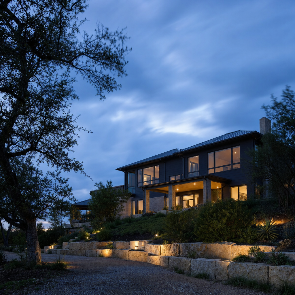
Austin’s residential land development ecosystem operates within a rigorously enforced regulatory framework, where site grading and drainage plan sheets are under close scrutiny by both the City’s Development Services Department (DSD) and the Watershed Protection Department. Compliance is a drawing-driven process: impervious cover, CEF buffers, ESC details, and permanent and temporary stormwater controls must be methodically coordinated, annotated, and dimensioned to pass the realities of plan review, inspection, and final job-site outcomes. Every line weight, hatch, and call-out is critical. The integrated workflow from schematic grading concept to final inspection follows Austin’s locally amended 2021 IRC, Land Development Code (LDC) Chapters 25-7 and 25-8, and the Environmental Criteria Manual (ECM). Each step is loaded with drawing-specific code references, tabulated dimensional constraints, departmental mark-ups, and a documented history of typical redlines.
Detailing Impervious Cover Calculations and Critical Environmental Feature (CEF) Setbacks on Austin Site Plans
Impervious Cover Graphic Conventions and Zoning-Specific Area Call-Outs
Impervious cover-a pivotal environmental metric-must be clearly depicted with drawing sheet clarity to satisfy Austin City Code §25-8-61 and §25-8-62, as locally amended. City reviewers frequently cite “Verify and correct impervious cover calculations to ensure compliance with zoning district limitations” and “Show percent IC and area IC by zone.” Plan sheets for SF-2 or SF-3 (the city’s predominant single-family residential zoning districts) set the maximum allowed impervious cover at 45% of the lot area (LDC §25-8-63).
Common best practice divides impervious cover into existing (light gray/pale crosshatch, solid outline), to be demolished (diagonal hatch, dashed outline), and proposed (dark/solid fill hatching, bold outline). All IC must be quantified on the “Site Plan - Grading” (C3.x) sheet, typically in a tabulated box adjacent to the title block:
- Existing IC (SF): (label on-plan with area call-out tags and hatch legend)
- Proposed IC (SF & %): (tag all new patios, driveways, additions individually; sum at summary table; note “Total IC = X SF/X%”)
- Zoning District Maximum IC: (call out, “Per SF-3, max IC = 45% lot area”)
Dimensioning for each impervious element (flatwork, buildings, roof overhangs, decks if non-raised, etc.) must be explicit-no ambiguous linework. For instance, “PROPOSED DRIVEWAY: 18’x38’ = 684 SF, DARK GRAY HATCH, OCCUPIES 12.4% OF TOTAL IC.”
Critical Environmental Features-Delineation, Symbol Legend, and Setback Dimensioning
All Critical Environmental Features (CEFs) must be plotted, dimensioned, and buffered as per LDC §25-8-281 and related sections. Common CEFs on Austin ridgetops and creekbed-adjacent lots include springs, riparian forests, bluffs, wetlands, and sinkholes. Their mapped extents require:
- BOLD dashed lines (distinct legend symbol): buffer perimeter
- Standardized annotation: e.g., “CEDAR BLUFF-150’ CEF BUFFER, SEE DETAIL 2/C3.2”
- On-sheet setback dimensions: “150’ SETBACK-MEASURED FROM EDGE OF BLUFF TO LIMIT OF SITE DISTURBANCE” for general CEFs; “25’ FROM CWQZ” for Critical Water Quality Zone setbacks (§25-8-92)
Buffer areas require a specific hatch pattern (diagonal crosshatch with light fill), and any encroachment-grading, construction, irrigation, or utilities-will trigger city comments. For instance: “Proposed terrace violates 150’ CEF buffer, revise location or submit for CEF exemption per LDC §25-8-281(C)”. Plan sheets must show not just location but clear call-outs with buffer distances from both proposed and existing construction.
Required Environmental Notes and Drawing-Sheet Annotations
- “Total impervious cover shall not exceed 45% of total lot area, per LDC §25-8-63.”
- “Critical Environmental Features and their buffers shall remain undisturbed. No construction, utility installation, wastewater disposal, or irrigation permitted within these zones, per LDC §25-8-281.”
- “All work must maintain specified setbacks from CEFs and CWQZs as labeled, refer to site legend for buffer dimensions.”
Prevalent Plan-Review Triggers for Redlines and Corrections
- Impervious cover errors: Overlap of existing/proposed IC, missing deck/flatwork, or calculation omission. Comment: “Discrepancy in impervious cover table; sum does not match plan area call-outs.”
- Insufficient CEF mapping: “Critical Environmental Feature exists within 300’ of project; show buffer, label exact setback, and add plan note prohibiting disturbance.”
- Encroachment violations: “Proposed construction within CEF or buffer. Must revise location or submit findings of no adverse impact per LDC §25-8-281(E).”
Plan drafters must proactively dimension all buffers, provide keyed call-outs, meticulously tabulate IC, and maintain clear separation of legends/symbols for each category.
Drafting Erosion and Sediment Control (ESC) Plans for Austin Residential Construction
Mandatory Temporary ESC Details-Call-Outs, Sections, and Material Specs
Austin’s code-mandated temporary erosion controls are heavily drawing-driven (ECM Appendix P-1, LDC §25-8-181-183). Typical plan-set convention places a “ESC Site Logistics Plan” (C4.x) with the following:
-
Silt Fence (COA STD 642S-1):
- Perimeter: solid heavy line, labeled with typical symbol.
- Plan notes: “SILT FENCE TO BE INSTALLED ALONG DOWNHILL PERIMETER OF DISTURBED SOILS; SEE DETAIL 5/C4.2.”
- Section detail: “36” MIN. HEIGHT, POSTS @ 6’ O.C., 6” FABRIC EMBEDDED BELOW GRADE, 18” POST EMBEDMENT MIN., ASTM D6461 GEOTEXTILE.”
- Call-out: “LIGHT DASH FOR EXISTING, DARK SOLID FOR PROPOSED.”
-
Rock Berms (COA STD 639S-1):
- Graphic: lumpy dashed contour, labeled “ROCK BERM 18” HIGH x 4’ WIDE, 3-5” WASHED ROCK, 20GA WOVEN WIRE SHEATH.”
- Note: “Install immediately down-gradient of fill stockpiles, as shown.”
-
Stabilized Construction Entrance (COA STD 641S-1):
- Location: bold border rectangle at all site ingress/egress points, labeled “STABILIZED CONSTRUCTION ENTRANCE, 50’ LONG x 20’ WIDE MIN., 6” WASHED ROCK OVER NON-WOVEN FILTER FABRIC.”
- Legend symbol and cross-section: “See C4.2/Detail 3.”
-
Inlet Protection:
- “INLET PROTECTION - SAND BAG OR ROCK SOCK, SEE PLAN/DETAIL, ALL ONSITE INLETS TO RECEIVE PROTECTION IMMEDIATELY PRIOR TO DISTURBANCE.”
- Plan view symbol: “CIRCLED INLET WITH TRIANGLE.”
-
Concrete Washout Area:
- Labeled rectangle, typically 10’x10’ MIN., “CONCRETE WASHOUT, LINED PER ECM REQUIREMENTS, LOCATION CLEAR OF TREE DRIP LINES AND CEF BUFFERS.”
Phased ESC Sequencing and Site Operations Notes
- Phase 1 (Pre-disturbance): Install silt fence, rock berms, stabilized construction entrance, and designate concrete washout before ANY grading or demolition-clearly illustrated on C4.1 with note, “NO SOIL DISTURBANCE UNTIL ESC MEASURES ARE IN PLACE.”
- Phase 2 (During construction): Maintain and repair ESC measures, implement inlet protection as storm structures are installed, stabilize exposed soils temporarily with hydromulch or cover per ECM 1.4.5.B.1.
- Phase 3 (Post-construction): Permanently revegetate disturbed soils, remove temporary ESC devices upon approval by city inspector.
City of Austin DSD Redlines and Onsite Compliance Deficiencies
- “Inadequate ESC for disturbed area-expand silt fence and add additional inlet protection.”
- “Failure to show ESC at property boundary-show ESC measures along all downstream and side boundaries.”
- “Missing stabilized access point detail-add full COA STD 641S-1 cross-section.”
- Jobsite installation call-outs: “ESC not installed per plan at east lot boundary; site subject to STOP WORK order unless corrected.”
Detail keys and plan-section referencing (“SEE DETAIL 5/C4.2”) are crucial. All materials must reference recognized standards; for example, “Geotextile per ASTM D6461, washed rock per COA STD.” Inspectors cite fabric/installation substitutions as corrections.
Designing and Drafting On-Site Stormwater Management for Positive Drainage
Topographic Graphics: Contour & Spot Elevation Conventions
Plan reviewers in Austin commonly redline, “Insufficient positive drainage shown from structure-provide spot elevations, 10’ grid,” or, “Flow arrows missing, cannot confirm drainage away from building.” The grading plan must illustrate both proposed and existing 1’ contours:
- Existing contours: Light dashed lines, labeled every 2’ with EL (elevation) call-outs.
- Proposed contours: Solid, slightly heavier; label at every interval intersecting walks/driveways/structures; use call-out bubble, e.g., “EL. 527.00 (PROP).”
- Spot Elevations: At every building corner, entry stoops, highest/lowest points along the perimeter, midpoints of swales and drainage breaks-preferably in a 10’x10’ grid pattern.
Positive drainage away from foundations is a code non-negotiable (IRC R401.3): “Grade shall fall a minimum of 6 inches within the first 10 feet away from foundation walls.” When a 10’ clearance is unavailable, plan notes must call for swales or drains to intercept water per code comments.
Permanent Drainage Features: Drawing and Connection Details
-
Swales:
- Plan: Solid, bold centerline with hatching for limits, labeled with start/end spot elevations and flow arrows.
- Cross-section detail: Bottom width 2’ min., depth 6-12”, side slopes MAX 3:1, longitudinal slope MIN 1% (0.5-2% preferred); base/sides called out as “VEGETATED, NATIVE GRASS, PER ECM 1.2.0D.”
- Section call-out: “SEE SWALE SECTION 2/C3.3.”
-
Area Drains & French Drains:
- Symbol convention: “Solid circle w/ leader; labeled ‘AREA DRAIN 4” PVC @ 1% MIN. SLOPE, CONNECT TO DISPERSION TRENCH AT 42’ FROM FOUNDATION’.”
- Section: Trench detail “12-18” wide by 18” deep, 4” perforated SDR-35 PVC, #57 open-graded stone, non-woven geotextile wrap, daylighted to legal discharge.”
- Include invert elevations at entry/exit points.
-
Culverts (Driveway):
- Material: “18” RCP (reinforced concrete pipe) or approved equal.”
- Dimension and label: “Culvert invert EL. 516.5, 20’ long, connects ROW gutter to on-lot swale.”
All outlets must terminate to a “legal point of discharge” identified on-sheet: “Discharge to Water Quality Control Facility per LDC §25-7-61(B),” or “Sheet flow to street ROW per City Drainage Criteria Manual 2.8.1.”
“No adverse impact” documentation must accompany final grading plan sets: provide supporting calculation narratives (“Proposed post-construction peak flow not greater than pre-dev, see attached HEC-HMS summary, per ECM 1.6.7”).
Plan Review Redline Examples and Preventive Drawing Solutions
- “Insufficient positive drainage shown: revise spot elevations, provide flow paths.”
- “Flow path terminates at adjacent property: revise swale/area drain grading to discharge on-site per DCM 2.7.0B.”
- “Inadequate storm sewer connection details: provide pipe size, material, inverts, and detail reference.”
The most successful drawing packages include a flow arrows legend, standardized call-outs (e.g., “SEE DRAIN DETAIL 3/C5.2”), and clearly cross-referenced calculation supplements.
Incorporating Water Quality BMPs and Permeable Solutions in Grading Plans
Water Quality BMP Graphic Standards and Cross-Section Detailing
ACC Sections 25-8-181 to 25-8-188 and ECM 1.6-1.9 require that any project over the water quality threshold (per ECM 1.9.0; typically >20% impervious cover or over threshold size) integrate water quality BMPs on both plan and detail sheets. Typical standards:
-
Rain Gardens (Bioinfiltration Basins):
- On-plan: Text label “RAIN GARDEN (RG), CONTRIBUTING DRAINAGE 1,280 SF IC, DESIGNED FOR 0.8” WQV.”
- Keyed cross-section: “12” ENGINEERED SOIL, 4” PERFORATED PVC UNDERDRAIN (ASTM D3034), 6” SAND FILTER, NATIVE VEGETATION, OVERFLOW PIPE TO DISPERSION TRENCH.”
- Hatch legend: layered gravel, sand, planting media, geotextile per ECM cross-section B.4.
-
Permeable Pavement:
- Plan: “PERMEABLE PAVER DRIVEWAY, CONTRIBUTING IC 720 SF” (area highlighted with discrete hatch and symbol ‘PP’).
- Section: “3.125” PERMEABLE PAVERS, 2” BEDDING #8 STONE, 6” OPEN-GRADED BASE (ASTM #57), SEPARATION FABRIC ASTM D4491, INCLUDES EDGING, NO-FINES BACKFILL.”
-
Dry Wells:
- Plan: “DRY WELL, CONTRIBUTING ROOF AREA 340 SF; LOCATED 15’ FROM FOUNDATION.”
- Detail: “4’ DIAM. x 6’ DEEP PRECAST CONCRETE CHAMBER (ASTM C478), 8” GRAVEL SURROUND, OVERFLOW AT 18”, 4” PVC OVERFLOW TO GRADE.”
Sizing Calculations and Drainage Area Call-Outs
All BMPs require:
- Drainage area call-out on plan: “CONTRIBUTING DRAINAGE 1,280 SF IC.”
- Capture volume calculations per ACC §30-5-213(B): “WQV = 0.5” runoff from all IC, plus 0.1”/10% IC over 20%. Rain garden sized for total capture.” Provide WQV summary on plans, cross-section area, and storage depth.
A common redline - “BMP SIZING INADEQUATE FOR CONTRIBUTING IMPERVIOUS AREA”-occurs when drainage areas are undercounted or capture volume math is missing or not cross-referenced to drawing footprint.
Overflow, Detail Cross-References, and Long-Term Maintenance Notes
Each BMP detail must show overflow paths with annotation, i.e., “OVERFLOW TO AREA DRAIN AT EL. 528.3, SEE SHEET C3.4 / DETAIL 7.” Permeable pavement details must include “NO UNDERDRAIN” (if infiltration), or “UNDERDRAIN OUTLET TO DRAINAGE SWALE” (if specified).
Plan sheets require explicit O&M (Operations & Maintenance) notes:
- “Property owner responsible for inspection and maintenance of all water quality controls per ECM 1.6.7.”
- “BMPs to be inspected quarterly and after any rainfall over 0.5”. Sediment and debris to be removed when depth exceeds 25% of design volume. Damaged vegetation or surface failures must be corrected immediately.”
Redlines commonly cite: “No overflow path shown”, “Insufficient cross-section detail”, or “Lack of O&M note-add protocol per ECM.” A clear detail-log referencing system (“SEE RG DETAIL 3/ C3.6”) for every graphical component is critical.
Navigating Austin’s Permit Workflow & Common Plan Review Redlines for Site Grading/Drainage
Permit Pathways and Required Drawing Components
Austin’s DSD, through the Austin Build + Connect (AB+C) portal, triages residential grading and drainage projects into (1) Site Plan Exempt (for 1-4 units on a legal lot with no floodplain effect), (2) Expedited Review, or (3) Full Building Permit w/ Site Plan. Each pathway has non-negotiable drawing elements:
- Benchmark and North arrow (every sheet)
- Property lines and all platted or unrecorded easements
- Existing/proposed 1’ contours and spot elevations at critical points (10’ grid, all corners, midpoints, swale inverts)
- Tree protection (for >8” DBH trees per LDC 25-8-604): tree survey, trunk call-outs, dripline and CRZ, and Tree Protection details
- Impervious Cover calculations (existing/proposed in table and on plan) per LDC 25-8-63
- Detailed ESC plan referencing COA STD 301-3, 639S-1, 641S-1, and city-adopted installation configs
- All buffers, setbacks, zoning overlays, and legal points of discharge mapped and dimensioned
Recurring Plan-Review Comments-Real Examples and Drawing Corrections
- “Spot elevations missing at rear corners-cannot verify drainage compliance.” Correction: Add labeled spot elevations at all foundation corners, with arrows indicating flow away from building (min. 6” fall in 10’ per IRC 401.3).
- “Flow arrows not shown-add for all proposed hardscape surfaces to demonstrate positive drainage.” Correction: Draft heavy-headed arrows at every drainage path; include legend “FLOW ARROW = PROPOSED SURFACE DRAINAGE.”
- “Swale cross-section missing-provide section with finished bottom width, side slopes (max 3:1), and longitudinal slope (min 1%).” Correction: Insert “SEE SWALE DETAIL 3/C3.4” and include a complete cross-section on detail sheet.
- “Impervious cover calculation exceeds SF-3 maximum-revise driveway size or patio area to comply with 45% limit.” Correction: Adjust plan, recalculate, and update summary table and call-outs before resubmission.
- “Tree protection plan not provided-add survey and tree protection notes/detail per LDC 25-8-604.” Correction: Add tree layer to plan, indicate CRZ, and include city standard tree fence detail in ESC plan set.
- “Inadequate detail for ESC device installation-add manufacturer’s specification or COA standard detail.”
Drawing and Annotation Strategies to Pre-Empt Redlines
- Comprehensive annotation: Every drawing should have spot elevations, flow paths, swale and BMP call-outs cross-referenced to details, and all drainage features dimensioned to code-minimum slopes and setbacks.
- Graphics clarity: Consistent line weights, unambiguous hatches, and full graphic legend (every sheet or on cover); avoid overlapping or “floating” contour lines-anchor with spot EL call-outs.
- Plan revision narrative: Respond to ALL City markups in resubmittals with a clear, itemized spreadsheet or cover letter: “Comment 3: Spot elevations missing at northeast corner-corrected, see C3.1 grid EL. 528.40.”
- Reference standard detail sheets: E.g., “SEE COA STD 641S-1-CONSTRUCTION ENTRANCE, INCLUDED ON C4.2.”
Specific Dimensions and Code-Driven Sheet Conventions-Summary Table
- Benchmark/North arrow: Each sheet
- Contours: 1’ intervals, solid for proposed, dashed for existing
- Spot elevations: 10’ grid, all corners, high/low points, drainage features
- Swales: 2’ bottom, 6-12” deep, 3:1 slopes, 1% min. grade
- Silt fence: 36” min. height, 6’ spacing, 6” below grade, 18” post embedment, ASTM D6461
- Rock berm: 18” H x 4’ W, 3-5” rock, 20ga wire mesh
- Stabilized entrance: 50’ L x 20’ W min., 6” washed rock, filter fabric base
- BMPs: Sized for water quality volume; rain garden 12” soil, 4” underdrain; permeable paver base 6” #57 stone, filter fabric ASTM D4491
Meticulous adherence to Austin code sections, graphic standards, and annotation best practices-combined with clear and code-referenced drawing sheets-reduces plan-review cycles and minimizes redlines. Each sub-discipline (grading, ESC, stormwater, water quality BMPs) connects directly to City requirements and review workflows. This drawing-centric process is the foundation for successful entitlement and efficient, compliant residential construction.
For drafting, design support, and plan review solutions tailored to Austin or Texas-wide residential projects, Kingsway Drafting & Design brings code knowledge and drawing expertise to every permit set.