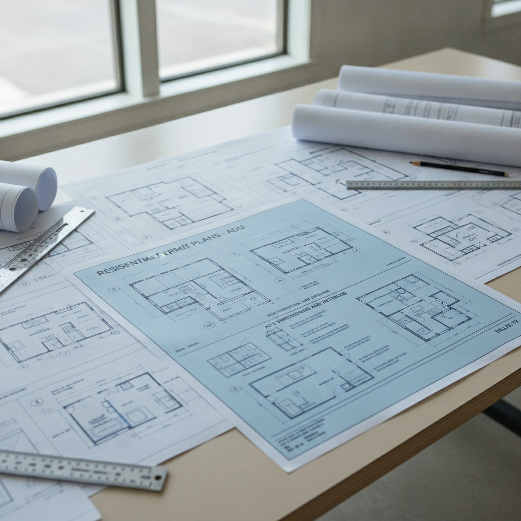
Precision in architectural drafting is mission-critical when detailing Accessory Dwelling Units (ADUs) in Dallas, Texas. The city’s adoption of the 2018 International Residential Code (IRC), with robust local amendments integrated into the Dallas Development Code Chapter 51A, presents unique requirements for plan sheets, dimensioning, code call-outs, and construction documentation. Drawings must not only reflect standard IRC-and-IBC conventions but also comply with Dallas’s distinctive zoning, fire safety, structural, and utility demands - all scrutinized through fastidious permit plan reviews and often amended in the field with project-altering redlines.
Site Plan & Zoning Compliance for ADUs in Dallas
Dimensioning Property Lines, Setbacks, and Impervious Cover on Plan Sheets
On site plans for ADUs in Dallas, particularly in Single-Family Attached (SF-A) and Single-Family 5,000 (SF-5) districts governed by Dallas Development Code Chapter 51A (Division 51A-4.400), property lines and setbacks must be explicitly dimensioned. Plan sheets must show:
- Front Yard: Minimum setback 25 feet, dimensioned perpendicular from the property line to the leading edge of the structure (ADU).
- Side and Rear Yards: Minimum 5 feet setback, legibly labeled from both the side and rear property lines to the nearest projection of the ADU (not to eaves unless permitted by code).
Redlines during Dallas plan review frequently state, “Dimension all setbacks from property lines to structure-dimension from eaves is not accepted.” Drafters should highlight these with callouts and dashed lines, using a site scale such as 1”=20’ or 1”=30’.
Impervious Cover Calculations are mandatory. The maximum lot coverage is 60% per SF-A and SF-5 requirements (Sec. 51A-4.112). All built structures, driveways, walks, patios, and outbuildings must be summed, shown in a key or schedule on the plan, alongside both area (sq. ft.) and percentage calculations. “Impervious coverage exceeds allowable 60%,” is a recurring plan-review note. Site plans must show these percentages clearly adjacent to the north arrow and legend; the title block should reference the calculation sheet number as well.
Dimensioning Building Separation and Access on Drawings
For ADUs detached from the main house, dimensioned distances between structures are compulsory. The Dallas Development Code mandates at least 15 feet between every group of eight single-family structures (Sec. 51A-4.209 (b)(7)), but most ADUs will require at least 10 feet separation between principal and accessory structures for fire and zoning. On site plans, dimension this separation “face-to-face,” and use centerline dimensions where common walls occur. Annotate with callouts such as “15'-0” min. clear btwn ADU & SFD per 51A-4.209.”
Vehicular and pedestrian access must be clearly labeled. Driveways and parking spaces require dimensions-width, length, and location-along with a “NOTES” box referencing Dallas Code Section 51A-4.602 for driveway visibility triangles (“No structure, fence, or planting >2.5 ft high in visibility triangle per 51A-4.602”). Pedestrian access should be traced from the public way or driveway to the ADU entrance, marking sidewalk widths (often 3’-0” or greater). Directional arrows are typically required by reviewers to make the pedestrian path explicit.
Parking, Zoning Notes, and Redlines
Dallas requires one off-street parking space per ADU, in addition to spaces for the primary dwelling (Sec. 51A-4.200). Parking location and numbers must be labeled with “1 ADD’L PARKING REQUIRED FOR ADU,” and drawn to standard space dimensions (9’-0” x 18’-0”).
Redlines frequently request, “Show & label existing and proposed parking spaces; provide surface treatment details (asphalt, concrete, etc.).” Annotate surface types, and include a legends key for hatching. On SF-A/SF-5 overlays, ensure labels such as “Zone: SF-5” and “Land Use: Accessory Dwelling Unit per 51A-4.510” appear in the plan’s data box.
Architectural Floor Plan Dimensioning & Egress/Accessibility for Dallas ADUs
Room Dimensions, Minimum Areas, and Sheet Call-Outs
IRC Section R304 requires all habitable rooms in an ADU to be at least 70 square feet, with no dimension less than 7 feet. On A-sheets, every room should be fully dimensioned (inside face to inside face), with a “ROOM SCHEDULE” noting each area. Dimension lines should avoid duplicating outside wall dimensions; instead, dimension each interior clear width/length for legal-habitability signoff.
Ceiling heights must be 7'-0" or greater in habitable spaces, and at least 6’-8” in bathrooms and hallways (IRC R305). Cross-reference elevations and building sections, using callouts: “CLG HEIGHT = 7’-0” MIN. PER R305.” Reviewers frequently redline, “Confirm ceiling height at ADU bathroom complies with IRC R305.1.”
Door/Window Schedules, Egress, and Glazing Code Call-Outs
The main egress door to the ADU must be side-hinged, with a clear width of 32 inches (2’-8”) and a height of at least 6’-8” (R311.2). On floor plans and schedules, tag the door “REQ’D EGRESS” and reference “32"x80" MIN. CLR OPENING PER IRC R311.2.” Always dimension from face-of-jamb to face-of-jamb, not just rough opening.
Sleeping rooms must have at least one egress window or an exterior door. R310.2.1 sets the minimum net clear opening at 5.7 square feet (or 5.0 sq. ft. at grade), with minimum clear opening width 20 inches and height 24 inches. Sill heights must not exceed 44 inches above finish floor. Window schedule symbols (e.g., W1, W2) should correspond to head/jamb/sill heights, and notation such as “EGR. WINDOW: 5.7 SF, 24” MIN H, 20” MIN W, SILL ≤44” AFF PER R310” must appear. Review redlines often state, “Provide window manufacturer cut sheets confirming code min. opening area & sill height.”
For glazing, ensure that the schedule includes square footage and percent calculation for exterior walls-IRC R303 requires glazing area not less than 8% of floor area, with 4% as openable area for ventilation. “WINDOW AREA DOES NOT MEET IRC MIN. GLAZING” is a typical review comment when these calculations are omitted.
Internal Clearances, Bathroom Layouts, and Fixtures
Bathroom layouts must maintain a 30”x60” minimum area for tubs/showers, a 15” minimum lateral clearance from the centerline of toilets, and 21” clear in front of all fixtures (R307, IPC 405.3.1), which should be shown as dimension strings on plans. For example, annotate: “TOILET: 15” MIN. CLR TO WALL, 21” MIN. CLR IN FRONT.” Plan reviewers commonly redline, “Show dimensioned code clearance at toilet/lav/shower for review.”
Floor plans should use standard architectural symbols (per AIA standards), with all fixtures keyed to a “PLUMBING FIXTURE SCHEDULE.” Incorporate ADA/TAS requirements if value >$50,000 triggers review by a Registered Accessibility Specialist (TAS §68.51), although single-family ADUs not used for public accommodation are typically limited to basic IRC accessibility standards (maneuvering clearances, threshold heights, lever hardware).
Egress Paths, Accessibility, and Redlines
Egress pathways must be unobstructed, minimum 36” wide, and confirmed on drawings by solid or dashed lines with related notes. “EGRESS PATH - 36” MIN WIDTH PER IRC R311.7” is a common callout. Landings at exterior doors must be at least as wide as the door and 36” deep-the drawing should clearly show “LANDING: 36” MIN. PER R311.3.” Plan review frequently flags, “Landing depth not dimensioned at ADU door-clarify on plan.”
When required, show turning radii (5’-0” clear) circles for wheelchair-accessible bathrooms/kitchens. Drawings should cross-reference the detailed enlarged plan, e.g., “SEE 3/A-401 FOR ENLARGED ADA BATH.”
Structural Framing & Foundation Detailing for Dallas ADUs
Foundation Plan: Pier & Beam / Slab-On-Grade Dimensioning
Foundation sheets (S-1) for ADUs in Dallas must distinguish between pier & beam and slab-on-grade systems, dimensioning the boundaries of the foundation, pier locations, and footings. Dimensions to property lines and offsets to primary structures must also be provided. Indicate footing size, shape, and rebar layout:
- Pier & Beam: Footings min. 12” below grade, 16” wide (typ.), reinforced with 2-#4 bars continuous. Spacing, typically 6’-8’ o.c., must be labeled.
- Slab-on-Grade: 4” thick slab, perimeter beam 12”x12” min. with #4 rebar at 18” o.c., dimensioned per structural grid and clearly noted “SOG: 4” MIN THK, FTG: 12”x12” w/ (2) #4 BARS, TYP.”
Section cuts should be keyed: “SEE 1/S-501 FOR TYP. FTG DETAIL.” Plan reviewers at Dallas Development Services repeatedly comment, “Provide rebar schedule and detail at all footings,” so S-sheets must include a reinforcement legend with bar sizes, spacing, lap lengths, and concrete strength (“f’c = 3,000 psi min”).
Wall Bracing, Hold-Downs, and Strapping: Detail Conventions
Per IRC R602.10, braced wall lines are required on all ADU perimeter walls and shear walls. Wall bracing method must be annotated: “BRACE WALL LINE PER R602.10 W/ PLY SHEATHING SEE 2/S-502.” Braced panel locations are highlighted on the floor plan as thickened lines or hatching, with symbols cross-referenced to details for nailing/stapling patterns.
Hold-downs are required at each end of braced panels (R602.10.6)-key each location with a callout: “SIMPSOM HDU2 HOLDOWN-SPECIFY FOUNDATION ANCHOR MIN. EMBED 12” w/ 1/2”Ø BOLT.” Connection details must show all anchor bolt and strap spacing, including “STRAPS AS REQ’D AT ALL INT/EXT PANEL ENDS PER MANUF’R SPECS.” Reviewers frequently redline, “Provide type, location, and anchorage of hold-downs at each braced wall.”
Roof & Floor Framing Layouts, Anchoring, and Schedules
Roof framing plans (S-3) dimension all truss or rafter locations, with member sizes referenced to tables (IRC R802.5.1 for rafters, R502.3.1 for joists), span callouts, and grade/spec notes. E.g., “2x8 @ 16” O.C. D.F. #2, SEE SCHEDULE.” Collar ties (if required) or ridge straps must be shown in section, with “COLLAR TIES: 2x4 @ 4’-0” O.C. IN UPPER THIRD ATTIC, TYP.” noted.
Anchoring to address Dallas’s 115 mph wind zone (per IRC R301.2[4]) includes continuous load path detailing (anchor bolting at 6’-0” o.c. max, with larger washers, hurricane ties at all roof/ceiling connections). “ANCHORS: 1/2”Ø BOLTS @ 6’-0” O.C. w/ 15” MIN. EMBED, WIND LOAD 115 MPH EXPOSURE B PER R301.2(4).” Review redlines often target missing wind load calculations, “Provide wind load calc’s and show consistent anchorage for Exposure B.”
Frost depth is set at 12”, so all footing bottom elevations must be >12” below grade. Plans should reference: “BOTTOM OF FTG -12” MIN. PER IRC R403.1.4.1.”
PME System Layout & Utility Connection Details for Dallas ADUs
Electrical: Outlet, Lighting, and Panel Layouts
Electrical plans (E-1) must dimension every living space so no point is over 6' from an outlet (IRC E3901.2). Draw outlets on plan every 12' max, using “RCPT” symbols and dimension lines from wall edges. Kitchens require outlets at max 24" intervals on counters (E3901.4.1), shown directly above upper cabinets in elevation with callout: “GFI RCPT PER E3901.6, 24” O.C. MAX.”
Bathrooms must show at least one GFCI-protected receptacle within 3’ of each lavatory-dimension and note each on the plan. Main panels and subpanels must be mounted 6'-6" max to the top breaker, with clearance zones “30”W x 36”D x 78”H MIN. CLEAR” drawn and labeled for service access.
Lighting plan sheets must show switched ceiling lights in every habitable room (E3903.2) and stairway switches at each level (E3903.3). Circuit schedules must list AFCI/GFCI protection, amperage, wire type, and load calculations.
Mechanical (HVAC) Unit Placement and Duct Routing
Mechanical plans (M-1) must detail the type and location of all HVAC equipment. Outdoor condensers must be “ON CONCRETE PAD, MIN. 3’ CLR TO WALL, NOT IN EGRESS OR SETBACK,” labeled and dimensioned. Indoor units (furnaces, air handlers) are dimensioned to allow minimum code-specified clearances for servicing (usually 30” at control side), with ductwork sketched in plan and reflected ceiling, and callouts referencing insulation requirements (“R-6 MIN. DUCT INSULATION IN UNCONDITIONED SPACE PER IMC 603.9”).
Duct routing must not penetrate fire-rated assemblies unless proper fire-dampers are specified and noted. Callouts such as “FIRE DAMPER REQ’D AT RATED ASSEMBLIES, SEE 2/M-502” are flagged by reviewers when omitted.
Plumbing and Gas Rough-in, Trenching, and Metering Details
Plumbing sheets (P-1) require fixtures dimensioned to property/proposed meter, with rough-in locations keyed and dimensioned. Toilets, sinks, and showers must conform to clearance minimums (see earlier Plumbing Fixture Schedule). Gas lines are sized per IPC 402, with trunk and branch sizes labeled; “1” GAS MAIN TRUNK, REDUCE TO 3/4” BRANCH, SEE ISOMETRIC.”
Utility connections must show trenching profiles: “ELECTRIC: 18” MIN. BURIAL, WATER: 12” MIN.” Draw cross-sections with pipe/conduit material callouts, backfill notes, and backflow device locations (“1” REDUCED PRESSURE BACKFLOW PREVENTER (RPBP) PER IPC 608 LOCATED 12” MIN. ABOVE FINISHED GRADE”).
For metering, note “SEPARATE ELECTRIC/GAS METER FOR ADU PER DDS POL’Y” if required, or reference “SHARED (SUB) METERED SERVICES PER OWNER.” Plan reviewers may redline, “Clarify if ADU will be separately metered; provide location & spec’s for new meters.”
Fire Safety, Separation, & Life Safety Detailing for Dallas ADUs
Fire Separation Distances and Plan Callouts
Per 2018 IRC R302.1, exterior walls of ADUs less than 3’ from a property line must be 1-hour fire-resistance-rated, with no openings permitted. If 3’-5’ from the line, walls are still 1-hour fire-rated, but may have limited openings (25% max of that wall face). Over 5’, no rating required. Drawings must:
- Dimension ADU-to-property line using solid and dashed lines; annotate “1-HR RATED WALL REQ’D PER R302.1 SEE 1/A-601.”
- Label window/door areas within 5’ of property lines as “NO OPENINGS WITHIN 3’” or “OPENINGS = XX% OF WALL AREA, < 25% PER R302.1.”
For ADUs built near the principal dwelling, ensure fire separation walls or dual occupancy partitions are specified if per code, dimensioned “10’ MIN. SEP. PER LOCAL AMENDMENT,” and cross-referenced to rated assemblies.
Wall Assemblies, Fire-Rated Construction, and Field Mark-Ups
Wall types for required fire separation should be referenced with UL/ASTM tested designs. On wall sections and details, call out “1-HR WALL: (2) 5/8” TYPE X GYP. BD. EACH SIDE 2x4 STUDS @ 16” O.C. INFILL MINERAL WOOL R302.1(2).” For 2-hour walls, double up on layers, and show all fastener schedules. Firestop and draftstop locations in all concealed floor/ceiling and wall spaces must be drawn and annotated: “FIREBLOCK TOP/INT. WALL @ 10’ O.C. MAX, 1/2” GYP OR 3/4” LUMBER STRIP, SEE 2/A-602.”
Dallas local amendments sometimes address additional fireblocking or draftstopping, especially for two-story ADUs or those with attic conversions. Check most-recent amendments (IRC Ord. 29164). Reviewers frequently flag, “Missing fireblocking at floor cavities-add note to S/A sheets.”
Smoke/CO Detector Locations, Drawing Symbols, and Redlines
Alarms are governed by IRC R314 and R315, with Dallas amendments aligning tightly. Use plan symbols (e.g. ‘SD’ for smoke detector, ‘CO’ for carbon monoxide-circle with letter) and locate in:
- Every sleeping room
- Hallways/entries outside each sleeping area
- Each level (including basements, attics, when habitable)
All alarms must be hardwired, interconnected, with battery backup. Callout example: “SD - INTERCONNECTED, HARDWIRED, BATTERY BACKUP PER R314” or “CO - SEE ELEC. DEVICE SCHEDULE.” Typical review comment: “Show SD/CO locations on all floors per R314/R315. Provide detail/symbol legend.” Confirm manufacturer/model in schedule and cut sheets.
Sprinkler Systems, Draftstopping, and Local Requirements
Fire sprinklers are not universally required for ADUs in Dallas unless the ADU overlays trigger higher standards or multiple accessory units are added. Always check district overlays and amendments. Where required, callout: “NFPA 13D SYSTEM PER LOCAL ORD. SHOW PIPING/HEAD LAYOUT, CALCS TO BE PROVIDED.”
Draftstopping in floor/ceiling assemblies and attic partitions must be continuous and shown in cross-section details: “DRAFTSTOP: 1/2” GYP. BD. AT 50’ MAX. INTERVALS PER IRC R302.12,” with dashed lines and elevation markups denoting locations. Reviewers frequently add, “Provide draftstop detail for concealed attic spaces.”
Standard Drawing-Sheet Organization, Notations, and Review Conventions
Model Sheet Index and Sheet References
Title Blocks must include jurisdiction (“City of Dallas”), address, zoning designation (e.g., “SF-5”), project description (“Proposed Accessory Dwelling Unit”), and sheet number. Standard organization aligns as follows:
- C-1: Site Plan (dimensions, coverage, access, parking)
- A-1xx: Floor Plans, Room Schedules, Window/Door Schedules
- A-4xx: Enlarged Room/ADA Plans
- A-6xx: Wall Sections, Fire Assemblies, Details
- S-1xx: Foundation Plans, Framing/Bracing Layout, Schedules
- P/M/E Series: Plumbing, Mechanical, Electrical, Utility Details
Key Callouts, Legends, and Cross-Referencing
Legends must define all symbols: egress windows, fire-rated walls, fire alarms, PME devices, anchors, structural elements, and utility features. Use cross-references (“SEE 2/S-502 FOR PANEL ANCHORAGE”) and full-sheet legends, with “NORTH ARROW” and drawing scale at the lower right of each plan.
Annotations must tie back to Dallas’s code sections, e.g., “PER DALLAS DEV. CODE 51A-4.510,” and all referenced code must be cited on a “CODE COMPLIANCE MATRIX” (usually on G-1 or G-2). Plan markups typically ask for this matrix: “Add compliance matrix w/ applicable IRC/IBC/Dallas amendments cited by section.”
Review and Field Redlines: Most Common Plansheet Corrections
The following are repeatedly redlined during Dallas DDS plan review on ADUs:
- “Dimension all yard setbacks to property line, not eave.”
- “Provide square footage calculation for all impervious surfaces.”
- “Show and label all required parking for ADU-specify surfacing.”
- “Add egress window schedule-dimension opening, sill height.”
- “Detail foundation rebar and pier size per S-sheet legend.”
- “Hold-downs at braced wall panels not keyed-show on plan.”
- “GFCI outlets missing in kitchen/bath-add symbols and schedule.”
- “Omit wall opening or provide UL-rated assembly at fire exposure.”
- “Missing smoke/CO locations-revise floor plan/schedules.”
- “Fireblocking and draftstopping not shown-add detail and note.”
Failure to explicitly dimension, detail, or note any of these items all but guarantees a roundtrip in the EPRS (Electronic Plan Review System), significantly delaying issuance.
Concluding Note
Every dimension, schedule, legend, and callout on an ADU project sheet for Dallas ultimately reflects a dense mesh of zoning envelope, code-mandated separation, meticulous structural detailing, complex PME coordination, and relentlessly reviewed fire/life safety specification-each step demanding intimate code knowledge and precision in documentation. For integrated, Dallas-compliant, permit-ready ADU plans, the architectural drafting approach at Kingsway Drafting & Design meets the city’s expectations with clarity, accuracy, and code-tested expertise.