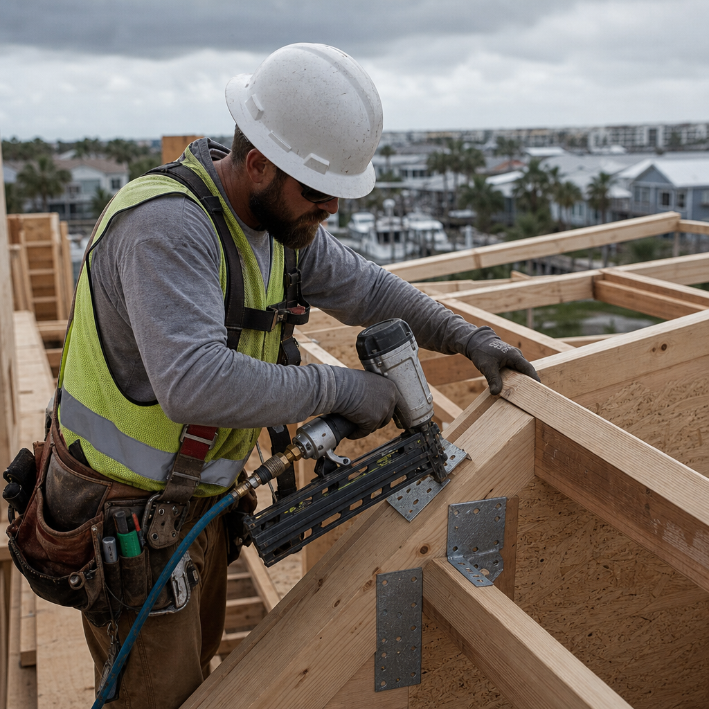
The structural resilience of residential roofs in Tampa, Florida, hinges on the translation of wind provisions from the Florida Building Code (FBC) and relevant standards-most notably ASCE 7-22-into actionable, review-ready, and inspector-friendly construction documents. Tampa’s adoption of the FBC 8th Edition, layered with Hillsborough County and City of Tampa amendments, shapes every aspect of uplift connection detailing, from load path schematics to installation notes for framing crews.
Translating FBC & ASCE 7 Wind Provisions into Load Path Diagrams and Uplift Resistance Values
Building Code Sections Governing Roof Uplift in Tampa
Roof uplift design for Tampa projects is dictated by the FBC 8th Edition (2023), which incorporates and amends key provisions from the 2021 IRC and IBC. Structural wind design is addressed primarily in FBC Chapter 16 (Structural Design):
- Section 1609 - Wind Loads: Obligates determination and documentation of site-specific wind loads, utilizing methodologies from ASCE 7-22.
- Section 1604.9 - Counteracting Structural Actions: Requires a distributed continuous load path, detailing how wind-induced forces (uplift, shear, overturning) travel through roof, wall, and foundation components.
- Section R802.11 (from IRC): Mandates the use of approved uplift resistance connections for rafters and trusses, with a table of required capacities based on rafter span, spacing, wind speed, and exposure category.
For engineering outside of prescriptive IRC tables-typical for larger homes or those using engineered trusses-plans must incorporate design loads from ASCE 7-16/7-22 sections 26-30, establishing cladding/component loads for the specific site exposure. Notably, plan reviewers regularly flag submittals lacking ASCE 7-22 references or clear wind speed designation (per Table 1609.3(1)), calling for explicit notation of both basic wind speed (Vult) and exposure category (likely C or D for much of Tampa near the bay).
Local Amendments and Zoning Overlay
In the City of Tampa, code administration is shaped by Hillsborough County’s Local Code §8-1 and amendments. Section 107.2.1.4 in particular is frequently cited in plan review for requiring construction documents to “demonstrate compliance with the wind criteria applicable at the site,” mandating plans show not just resistance values but the entire load transfer mechanism. Zoning overlays (such as “RS-50 - Residential Single Family,” “RM-16 - Residential Multi-Family,” etc.), while primarily affecting land use, also dictate certain structural thresholds for wind-resistance justification-especially for larger, taller infill projects in “transitional” urban residential zones.
Drawing-Sheet Practices for Wind Uplift Translation
Effective permit sets in Tampa distill code requirements into several core drawing and note conventions:
- Continuous Load Path Diagram: Schematic on the S1.1 (General Notes) or S2.1 (Roof Framing) sheet, often under “STRUCTURAL LOAD PATH DIAGRAM,” using bold leader lines and standardized connector symbols. This diagram shows the step-down from roof sheathing → rafter/truss seat → top plate → wall stud → wall base anchor.
- Uplift Resistance Notes: Tabulated connection schedule (see next section), directly referencing calculated pressures from ASCE 7-22 or prescriptive IRC/FBC tables. Typical note: “INSTALL SIMPSON H2.5A HURRICANE TIE OR EQUIVALENT EACH RAFTER/TRUSS TO EXTERIOR WALL. FASTEN PER TABLE BELOW. MIN. UPLIFT RESISTANCE: 700 LBS/CONNECTION.”
- Design Wind Speed Call-out: On cover sheet (G0.1) and again in Structural General Notes: “WIND DESIGN: Vult = 140 MPH, EXPOSURE C, ASCE 7-22, RISK CATEGORY II.”
Plan reviewers in Tampa routinely return sets missing one or more of these elements, notably marking: “Please provide clearly labeled continuous load path details and specify uplift values and connection locations per FBC 1609 and ASCE 7-22.”
Detailing Hurricane Clips and Straps: Proprietary & Generic Uplift Connectors on Plan Sets
Code and Product Call-Outs for Uplift Hardware
Per FBC-R802.11 and IBC-2304.10.4, all rafter and truss-to-top plate connections in Tampa must employ “approved connectors” (often called “hurricane ties”) with sufficient uplift capacity per calculated site wind load. Acceptable connectors are typically either ICC ES/Florida Product Approved proprietary clips (Simpson Strong-Tie, USP, etc.) or structurally equivalent generic straps meeting minimum 18ga. G90 galvanized steel standard.
On S2.2 Framing Plans and A5.x Detail sheets, explicit, unambiguous call-outs improve plan review and field installation outcomes. For example:
- “Simpson Strong-Tie H2.5A HURRICANE TIE @ EACH RAFTER/TRUSS SEAT, BOTH SIDES WHERE REQUIRED BY UPLIFT SCHEDULE. FASTEN W/ (5) 0.148" x 2.5" GALV. NAILS TOP, (5) BOTTOM. MIN. UPLIFT 590 LBS (DF/SP). SEE TABLE A3.2.”
- For larger uplift values: “SIMPSON H10AR TIE OR APPROVED EQUIVALENT FOR GABLED END FRAMES; SEE SCHEDULE FOR UPLIFT CAPACITY, INSTALLATION PER MFR.”
- For generic approaches: “18GA. GALV. TENSION STRAP EACH RAFTER/TRUSS, INSTALLED CONTINUOUS OVER TOP PLATE W/ (8) 10d NAILS EA END, SEE ENGINEERING NOTES FOR CAPACITY.”
Fastener schedule reference is always required by permit reviewers; missing nail size/quantity or simply specifying “per manufacturer” without a clear schedule routinely incurs this comment: “Provide connector installation details with fastener sizes, penetration, and approved anchor schedules. Do not reference ‘per manufacturer’ only.”
Uplift Capacity Schedules and Manufacturer Documentation
Roof schedules for Tampa plans must include an “UPLIFT CONNECTION SCHEDULE” (typically Table S3.1 or similar), cross-referenced in both plan view (“PER UPLIFT SCHEDULE, SEE DETAIL”) and in each relevant section detail. Entries include:
- Connection Location (e.g., typical rafter seat, gable end, valley/hips, intersecting walls)
- Connector Model (e.g., H2.5A, H1, H10AR, or “Generic 18GA Strap”)
- Nail/Screw Type and Quantity (e.g., “(5) 0.148" x 2.5" galvanized nails”)
- Tested Uplift Capacity (e.g., 590 lbs, 835 lbs, etc. per manufacturer)
- Florida Product Approval Number/Miami-Dade NOA if applicable
Example:
| Location | Conn. Type | Fastener & Qty | Uplift Limit (DF/SP) | FPA# |
| Each Rafter & Truss to Plate | Simpson H2.5A | (5) 10d x 2½" galv. nails | 590 lbs | FL12345-R4 |
| Gable End Rafters | Simpson H10AR | (8) 10d x 1½" galv. nails | 1,460 lbs | FL23456-R1 |
| Generic Strap | 18ga strap | (8) 10d ea end | 450 lbs | N/A |
City of Tampa plan reviewers increasingly require submittal of manufacturer cut sheets for all proprietary connectors at permit review, and redline any submittal lacking uplift tables or FPA/NOA documentation.
Material & Fastener Specifications
- Minimum Material: 18ga. G90 galvanized sheet steel
- Fasteners: 10d (0.148" x 2½") nails unless otherwise specified by APA/mfr. SDS screws (e.g., 3" Simpson Strong-Drive) for very high loads or engineered lumber, per manufacturer's ICC ES report
- Connection Placement: Both sides of each rafter/truss at gable ends; one side otherwise, unless uplift demands warrant double connectors
Manufacturer guidance and the FBC override “generic” solutions: “THERE SHALL BE NO SUBSTITUTION OF FASTENERS UNLESS APPROVED IN WRITING BY THE DESIGN PROFESSIONAL.” Omission of screw/nail length, count, or corrosion protection on plans is a sure route to a permit review hold.
Navigating Tampa Plan Review: Common Redlines, Plan-Set Revisions, and Uplift Deficiency Resolutions
Typical Plan Review Comments and How Uplift Details Are Flagged
Tampa Development Services Department plan reviewers focus on wind uplift adequacy and documentation. Frequent deficiencies cited in review memos include:
- "Please provide wind uplift calculations and continuous load path diagrams per FBC 1609/ASCE 7-22."
- "Fastener type, size, and spacing not specified for roof-to-wall connectors."
- "Florida Product Approval (FPA) or Miami-Dade NOA required for specified roofing materials/hardware."
- "Roof sheathing attachment schedule missing or does not meet FBC Table 2304.9.1 / R803.2.3.1."
Redlines in digital plan review often target missing connection call-outs in the “typical wall section,” incomplete or ambiguous uplift schedules, and missing cross-references (e.g., “SEE S3.2” not provided on S2.2 framing plan call-out bubbles).
Effective Drafter Responses: Revision Procedures and Documentation
- Cloud and Index Changes: Revised details are clouded in red, revision date and item listed in the revision block on each affected sheet as required by Section 107.2.1.4 (Hillsborough County Code).
- Full Plan Set Resubmittal: The City of Tampa requires attachment of updated full digital plan sets-never single updated sheets unless explicitly instructed, to ensure reviewers can cross-check connections throughout set.
- Direct Code Referencing: All narrative responses in the plan review portal reference specific code: “Revised S2.1 to show continuous load path per FBC 1609; uplift connection schedule provided per Table R802.11. FPA #s called out for all connectors and underlayment, see details A3.2 & S3.1.”
- Manufacturer Cut Sheets: Submitted with S3.1 or as separate PDFs, titled explicitly with project address and connector type (e.g., “Simpson_H2.5A_FPA-12345-3421_Wind_Uplift.pdf”). Reviewers require these highlight product approval stamp and load tables.
- Roof Sheathing & Fastener Patterns: Attachment details shifted from a generic note (e.g., “Install per code”) to explicit-“Minimum 7/16” OSB or ½” CDX plywood, fasten 6” OC at panel edges, 12” OC field with 8d common nails, see FBC 2304.9.1.”
Failing to address each redline in narrative and clouded drawing form will result in cyclical “RESUBMIT WITH NOTED DEFICENCIES ADDRESSED” comments.
Integrating Roof Uplift Connection Schedules and Call-Outs onto Architectural and Structural Plan Sets
Plan Sheet Cross-Referencing and Detail Numbering
Tampa structural plan sets are expected to integrate uplift detailing across multiple sheets with rigorous cross-referencing and clear numbering conventions, removing ambiguity in field and during permit review. Key approaches:
- Architectural Roof Framing Plan (A2.2 / RFP): Major uplift connection call-outs bubble all rafter/truss to top plate connections (“SEE DETAIL 3/S3.2”). Bubbles reference the detail number and destination sheet.
- Uplift Schedule Table (S3.1 or S2.2): This tabulates all required connectors and fasteners. Headed explicitly “ROOF UPLIFT CONNECTOR SCHEDULE” and referenced wherever “SEE UPLIFT SCHEDULE” appears in plan or detail.
- Enlarged Details and Section Cuts (A4.1, S3.x): Section lines (“SECTION 2/A4.1”) cut through eave/wall/plate intersections. Within each detail: connector exaggerated at rafter seat, annotation reading “(N) SIMPSON H2.5A W/ (5) 10d NAILS, SEE UPLIFT SCHEDULE.”
- Consistent Detail Numbering: All sheet call-outs use a system of “[detail number]/[sheet number]”-never ambiguous references like “SEE ROOF FRAMING DETAIL.” For example, “DETAIL 7/S3.2: RAFTER/PLATE UPLIFT CONNECTION (TYP).”
- Notes Section: “ALL ROOF-TO-WALL CONNECTIONS SHALL UTILIZE CONNECTORS AND FASTENERS INDICATED IN UPLIFT SCHEDULE. ALTERNATES BY SPECIFIC ENGINEER OF RECORD ONLY.”
Typical Plan Reviewer Feedback and Redline Patterns
Comments often reference insufficient cross-referencing as a cause of eventual field errors. Common feedback:
- “Please reference all uplift connector details and schedules in both plan views and section details.”
- “Section cut referenced in A2.1 does not align with corresponding detail on S3.1. Revise to clarify.”
- “Detail numbers must be consistent throughout full set.”
Field changes-especially incorrect hardware or missed connectors-are commonly traced back to insufficiently referenced or inconsistently numbered details.
Product Approvals and Material Schedules
Full compliance requires plan sets to make direct reference to Florida Product Approvals or Miami-Dade NOAs for each proprietary connector, listed in the “Uplift Connection Schedule.” Where generics are used and no FPA/NOA is available, “ENGINEERED EQUIVALENT ATTACHMENT PER S3.1” must be called out, and all generic hardware must be supported by PE-sealed test data in Tampa.
Sheathing, fastener, and wood species/grade are noted both in tabular and note form for clarity. E.g.: “SHEATHING: MIN. 7/16” OSB 24/16 APA RATED SHEATHING or ½” CDX, NAIL PER SCHEDULE.” Roof plan, wall section, and detail must reflect the same material and provide matching nailing/fastener schedule. Plan reviewers specifically check for this coordination.
Crafting Unambiguous Call-Outs & Inspection Checkpoints to Minimize Jobsite Rework
Drawing & Note Conventions to Prevent Field Mistakes
Unambiguous communication on permit documents is essential to reduce jobsite rework, failed inspections, and delays. Tampa’s high-wind risk and rigorous inspection culture demand:
- Connector Call-Outs: Directly in the plan or detail, always read: “SIMSPON H2.5A or EQUIVALENT, (5) 10d x 2½” GALV. NAILS EACH LEG, OR AS NOTED IN SCHEDULE.” Call-outs must make explicit whether single- or double-sided installation is intended.
- Fastener Details: “USE ONLY FASTENERS SHOWN IN UPLIFT SCHEDULE. SUBSTITUTE FASTENERS BY APPROVAL OF EOR ONLY. ALL NAILS GALVANIZED, MIN. 1½” PENETRATION INTO FRAMING.”
- Note on Wind Criteria: “WIND DESIGN: VULT=140 MPH, EXPOSURE C, RISK CAT II (ASCE 7-22). ALL ROOF-TO-WALL CONNECTIONS SHALL RESIST A MINIMUM OF 700 LBS UPLIFT (TYPICAL), 1000 LBS AT GABLE ENDS.”
- Highlight Inspection Points: “CONNECTIONS TO BE LEFT VISIBLE FOR ROUGH FRAME INSPECTION. DO NOT COVER UNTIL APPROVED BY BUILDING INSPECTOR.” Call out both in general notes and framing plan.
- Strap/Bent Hardware Drawing: Detail callout to read: “INSTALL HURRICANE STRAPS FLUSH TO FACE OF LUMBER-DO NOT BEND OUT OF PLANE. BENT OR TWISTED STRAPS SHALL BE REJECTED BY INSPECTOR.”
Field failures-missed connectors, wrong hardware, insufficient fasteners, or bent straps-trace directly to ambiguous or poorly coordinated sheet notes. Omission of nail count or “field verify per code” in the set virtually guarantees an inspection fail in Tampa.
Installation & Inspection Notes
- General Notes Sheet: “ALL ROOF UPLIFT CONNECTIONS TO BE INSTALLED EXACTLY AS SHOWN IN DETAILS AND UPLIFT SCHEDULE; NO SUBSTITUTIONS WITHOUT SEPARATE ENGINEER REVIEW.”
- Punch List / Inspection Checkpoints for Framing Crews:
- “ALL HURRICANE TIES INSTALLED SNUG TO RAFTER AND PLATE, NAILS FULLY SEATED.”
- “NO DAMAGED OR BENT CONNECTORS-REJECTED ITEM TO BE REMOVED/REPLACED.”
- “DOUBLE TIES AT GABLES AS CALLED OUT IN SCHEDULE.”
- “FIELD COORDINATE WITH INSPECTOR FOR VISUAL APPROVAL BEFORE INSULATING OR COVERING WALLS.”
The jobsite reality in Tampa further compels call-outs for corrosion resistance, as city inspectors require-“ALL ROOF CONNECTORS AND FASTENERS SHALL BE HOT-DIP GALVANIZED OR STAINLESS STEEL IN COASTAL EXPOSURES (ZONE C/D),” matching FBC guidance for coastal salt exposure zones.
Typical Mistakes and Plan Strategies for Prevention
- Incorrect Fastener Placement: Offset via enlarged detail showing nail pattern with arrows and “NO NAILS WITHIN 1" OF EDGE.”
- Bent or Improperly Bent Straps: Three sequence diagrams showing correct install, plus note: “DO NOT BEND STRAPS OUT OF PLANE. BENDS GREATER THAN 5° TO FIT FRAMING ONLY IF PER MANUFACTURER CHART.”
- Substituted Hardware: Note: “NO HARDWARE SUBSTITUTION WITHOUT WRITTEN EOR APPROVAL ON SITE.”
- Missed Connection Points: “COUNT OF REQUIRED UPLIFT CONNECTORS TO BE CHECKED AGAINST SCHEDULED FRAMING AND NOTED TO FRAMING SUPERINTENDENT PRIOR TO DRY-IN.”
Specific Connection Rating Benchmarks Per Wind Zone
Latest FBC amendments (see proposed 9th Ed.; RoofVista, 2026) set minimum uplift per connection:
- 120-140 mph (most of Tampa): 500 lbs/connection (minimum)
- 140-160 mph: 700 lbs/connection
- 160+ mph & HVHZ: 1,000 lbs/connection
Most plans for Tampa inside the 140-160 zone will require H2.5A or H10/H10A ties, with both documentation and installation checked with a focus on uplift ratings and visible, correct, non-corroded fasteners. Building inspectors-faced with hurricane exposure-will not pass framing unless these elements are clearly documented, matched to as-built install, and left visible until inspection.
Conclusion
Every drawing, note, and schedule in a Tampa roof permit set must work synergistically to meet the region’s wind-lateral requirements-starting with explicit translation of FBC and ASCE 7 provisions into the drawings, selecting connectors with code-mandated or engineered uplift ratings, integrating hardware and fastener details into fully cross-referenced drawings and schedules, rapidly resolving plan review comments with code-cited revisions, and ensuring field clarity for crews and inspectors to eliminate the preventable rework endemic to vague details. Using these rigorous strategies, drafters support strong, safe, and compliant homes for Tampa’s high-wind environment-exactly what Kingsway Drafting & Design delivers on every project.