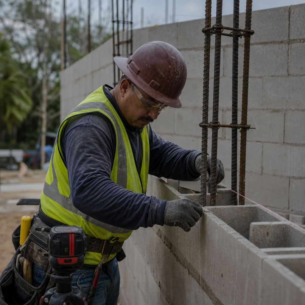
Reinforced concrete masonry unit (CMU) wall systems in Orlando, Florida, must answer to a rigorous regime of code requirements, highly specific schedule call-outs, and the realities of regional wind, flood, and seismic demands. Properly detailing grouting and rebar schedules on residential permit plans is a non-negotiable precondition for passing plan review-especially given the City of Orlando’s technical amendments to the Florida Building Code (FBC)-and a decisive factor in streamlined construction, inspection, and final occupancy.
Codes and Amendments: The Regulatory Framework for Masonry Wall Detailing in Orlando
Florida Building Code Adoption and the City of Orlando Amendments
Orlando, Florida, requires all residential construction to comply with the Florida Building Code, 8th Edition (2023), adopted alongside local amendments as codified in Chapter 13, City of Orlando Code of Ordinances sections 13.4-13.5. These amendments overlay additional technical conditions specific to Central Florida's climate, floodplain, and wind-borne debris regions. For masonry, this means stringent engineering requirements for wall reinforcement and grouting, especially in R-1 and R-2A (low-intensity residential) and R-3A/PD (higher density and planned development) zoning districts vulnerable to wind uplift and moisture intrusion.
Code Sections Directly Governing Detailing
- IRC Section R606-R608: Sets forth the requirements for the design, reinforcement, and grouting of masonry structures.
- IBC Chapter 21: Controls engineered masonry, including detailed provisions for reinforcement requirements, maximum spacing, grout bonds, and inspection mandates (mirrored and modified by the FBC).
- Florida-specific Amendments: Notably, FBC Residential 404.1.2.1 and amendments under Section 13.5 often trigger special commentary for wind and flood conditions in Orange County.
For residential projects, these mandates apply to everything from single-family homes to townhomes and duplexes-especially where CMU is relied upon for structural stability in loadbearing, braced wall, basement retaining, or wind-resistive applications.
Reading and Crafting Plan Sheet CMU Wall Details: The Language of Reinforcement & Grout
Rebar Schedules: Specification, Placement, and Code-Driven Detailing
A rebar schedule in Central Florida is not a generic list-it's a codified table, typically shown on Structural (S-) or General Notes plan sheets, distinctly calling out:
- Bar mark/identifier (e.g., "V1", "H2")
- Type, size, and grade (
#5 ASTM A615 Grade 60) - Spacing (
16" O.C. Vertical; 32" O.C. Horizontal) - Locations (e.g., “@ each end of wall, each side of opening, both sides of control joint”)
- Lap lengths (e.g., “#5 vert. rebar: 30” min. lap splice per ACI 530.1-13 Table 6”)
- Development and hook requirements for corners, intersections, and changes in wall height
- Field bending instructions (rare, but sometimes noted for site-adapt situations)
Plan reviewers in Orlando routinely redline “verify bar spacing/lap not called out” or “missing code reference for vertical and horizontal reinforcement” if schedules are incomplete. Typical comments include: “Submit structural notes indicating reinforcing schedule per FBC-R606.11.1 and lap lengths per ACI 318 Ch. 9”.
Grouting Schedules & Patterns: Complete Fill, Partial Fill, and Call-Outs
Orlando’s permit reviewers expect clear indication where grout is required, per code and engineering analysis. Grout call-outs are conventionally rendered as:
- Section cut symbols/legends designating fully grouted, partially grouted, and ungrouted cells (e.g., hatch patterns or grayscale blocks on wall sections)
- Notes adjacent to wall sections or keyed details specifying:
“GROUT FILLED CELLS AT ALL VERTICAL REBAR, CORNERS, WALL INTERSECTIONS, AND AT 48” MAX. O.C. WHERE NOTED, PER STRUCTURAL SCHEDULE” - Mix and strength call-outs:
“Grout to be fine or coarse as specified in ASTM C476, 2,000 psi minimum compressive strength @ 28 days” - Symbolic notation for grout pours (e.g., “G” in filled cells on plans/elevations, crosshatched or keyed color per office standard)
Inspections and special inspection requirements often demand explicit notes: “Special inspection required for all reinforced masonry grouting, per FBC107.3.5 and IBC 1705.4”.
Dimensioning and Detailing: Wall Geometry, Openings, and Reinforcement Position
Standardized Nominal and Actual Dimensions: Field and Permit Considerations
CMU wall geometry must present coherent, verifiable data on the plan to avoid confusion in the field and during the plan review. The following dimensional standards apply:
- Minimum nominal CMU size of 8" x 8" x 16" (actual: 7-5/8" x 7-5/8" x 15-5/8"); called out on architectural elevations (“8” CMU WALL, TYP.”) and on structural sections.
- Wall thickness-explicitly dimensioned from finished exterior face to finished interior (“8” CMU core, 7/8” stucco, ½” furring + drywall”).
- Vertical rebar centerlines dimensioned from wall face (“Locate #5 vertical rebar 4” from exterior CMU face, typ.”, for continuous bond pattern compatibility).
- Precise locations for piers, control joints, and lintels-all must be keyed with structural tags (e.g., “L1, CJ1”) referenced to schedule and detail sheets.
For corner and wall intersections, dimensions for bar bends, hooks, or extensions are dictated by detail tags and labeled as such: “Hook horizontal bar 12” min. into return wall, typ.”
Openings: Consolidation, Lintel Reinforcement, and Grouting Detail
Windows and doors in CMU walls must be handled with explicit references for reinforcing and grouting to avoid classic permit redlines: “Provide reinforcing schedule for masonry above door and window openings per FBC R606.11.2”. Good practice includes call-outs such as:
- “#5 vert. bars @ each jamb, full height, grout all jamb cells.”
- “Provide 2-#5 hor. bars continuous in bond beam above opening, embed 24” min. each side. Grout solid bond beam.”
- Lintel/beam sections with keynotes referencing schedules (“Section L1, see S-502”).
All such locations should be tied to a comprehensive wall schedule and rendered explicitly in both plan and elevation views-ambiguity is a top plan review complaint.
Orlando Permit Plan Workflow: Typical Review Comments, Redlines, and Approvals
Submittal and Review Expectations in Orlando’s Permit System
The City of Orlando uses FastTrack Online Services for digital permit applications and plan uploads (orlando.gov). For projects in R-1/R-2A or R-3A/PD, residential construction documents for CMU walls must include structural schedules, detail sheets, general notes, and code compliance certifications per FBC 107.2.1. Typical submission materials include:
- S-Series drawings (plans, sections, schedules; keyed detail sheets)
- Architectural elevations and wall sections referencing structural notes
- General notes with explicit code edition and amendment citations
- Special inspection statement (where required under FBC Ch. 17/IBC 1705.4)
Common Redlines and How to Avoid Them
- “Missing rebar schedule or size/spacing undefined”: Always include a tabulated schedule and call-out, even for one-off, site-specific wall conditions.
- “No lap length or splice details for vertical steel”: Tag lap lengths in schedule columns; cite applicable code table (“Lap splice per ACI 318-14 Ch. 9, 30” typ. for #5”).
- “Grout pour height exceeds code limits for cleanout”: Indicate for lifts over 5’ that cleanouts are required, per ASTM C476 Commentary and FBC R608.6.
- “Special inspections not noted where full grout/reinforced schedule”: Add explicit text box (“Special inspection per FBC 110.3.8/IBC 1705.4 for all fully grouted/reinforced CMU walls”).
Responding proactively with precise, code-cited notations eliminates most plan review cycle delays for CMU wall detailing in the City of Orlando.
Site Execution and Field Verification: From Drawings to Built Walls
Translating Schedules and Call-Outs into Field Practice
Quality construction in Florida’s humid, storm-prone environment stands only as strong as the clarity of its permit documents. On the job site, the “language” of the plan sheets must be unambiguous for field layout, inspection, and punch. Key translation points from typical S-sheets and details include:
- Clear rebar tags (V1 for vertical, H1-H2 for horizontal) with (if required) color-coded bar bundles on site and matching field mark drawings
- Grouting patterns directly referenced on field signage-such as “Grout all cells w/ rebar and at every second cell at corners/intersections”
- Field inspection cards or checklists paralleling the drawing notes (“Lap lengths at least 30”; grout lift not exceeding 5’; verify bar type & spacing”)
Special Inspections and Field Documentation
Inspection notes drive field scheduling: many residential projects in Orlando must have a special inspector (licensed professional or masonry inspection agency) present at pour, particularly when walls are fully reinforced or over 5 feet in height, per IBC 1705.4 and FBC technical amendments. Complete redline avoidance hinges on schedules that clearly key inspection requirements from the outset:
- “Special inspection of rebar placement and grout fill, per approved schedule and FBC 110.3.8”
- “Provide masonry grout placement log and inspection report to job-site”
Photos, batch tickets for grout, and as-built sketches matching marked-up structural sheets are the norm for inspection and eventual permitting closure.
Material Specifications and Notations: Practical Sheet Examples and Best Practices
Proper Code Citation and Material Specs
Direct notations on plans must leave no doubt as to the compliance path chosen. The following sample notes, used widely in successful Orlando submissions, reflect both industry best practice and permit reviewer expectation:
- “CMU: ASTM C90, 8” x 8” x 16”, 1,900 psi min. compressive strength at 28 days.”
- “Grout: ASTM C476, 2,000 psi minimum. Fine or coarse as appropriate for wall size/lift.”
- “Mortar: Type S, ASTM C270, 1,800 psi min.”
- “Rebar: ASTM A615, Grade 60, deformed. All lap splices per ACI 530.1 Sec. 6.1.”
- “Install #5 vertical bar @ 16” O.C. in all grouted cells, full height, lap 30” minimum.”
Embed these specs in both the structural notes sheet and as call-outs in wall section/details. This double reinforcement in the documentation dovetails with plan review checklists-removing ambiguity for reviewer, inspector, and field installers alike.
Legend, Symbology, and Sheet Layout: Visual Clarity for Field and Reviewer
In addition to text schedules, Orlando expects modern symbol legends linked to wall sections and elevations. Examples from accepted commercial and residential plan sets include:
- Grout hatch or fill symbol (dotted or diagonal-grid fill in relevant wall section/block)
- Bar leader/arrows with scheduled mark (e.g., “V1-#5” or “H2-#4”) for clarity
- Section tag “bubble” call-outs (“See Detail 4/S-503” for every unique wall/lintel/jamb)
- Color or grayscale keys for partial- versus full-cell grouting built into legend box
- Explicit table reference to plan sheet number and detail location in schedule column
Each of these visual strategies accelerates plan approval and reduces odds of costly field rework due to inconsistent interpretation.
Wall Types, Zoning, and Site Specifics: Responding to Orlando Urban Contexts
Zoning, Site Constraints, and Their Impact on CMU Wall Detailing
Residential exterior and retaining CMU walls are strongly influenced by project location within the City’s zoning schema. In R-1 (single-family) and R-2A (duplex/triplex), allowable wall heights, setback restrictions, and floodplain overlays (especially near Lake Eola, West Lake, or flood-prone downtown subdistricts) may call for:
- Flood-resistant walls with base elevation keyed on survey and referenced on every relevant wall/foundation section (“Top of CMU stem wall, FFE +2”, Per FBC R322, Flood Hazard Areas”)
- Enhanced wind-load reinforcing, typically requiring reduced O.C. spacing (“#5 vert. @ 16” O.C. maximum, all cells grouted for exposure category C, per FBC 1609”)
In higher-density R-3A and Planned Development (PD) districts, interaction with adjacent parcels and shared-ownership walls frequently triggers additional coordination notes-especially for party-wall grouting, CMU furring details, and reinforcing trade-offs for noise or fire-resistance.
Process Coordination and Sequencing
Residential projects in Orlando must coordinate wall detailing with slab, roof, and fenestration packages. Seamless plans feature schedules and details integrated with slab dowel call-outs (“Dowels: #5 @ 16” O.C., 30” embed in stem wall, min. 6” into slab, typ.”) and with registered engineer review stamps when over prescriptive code thresholds. Plan reviewers expect both on sheet (“EOR: John Doe, PE, Date”) and in FastTrack online submittal metadata.
Integrating Code, Schedule, Construction, and Permit Approval: A Durable Approach
Summary Table: Common Call-Outs for Orlando CMU Walls
- Reinforcing steel:
#5 @ 16” O.C. vertical; #4 @ 32” O.C. horizontal, lap as scheduled - All cells with rebar and at corners, jambs, and intersections to be grouted solid
- Mortar: Type S, 1,800 psi minimum, match color at exposed CMU walls, per plans
- Bond beam: Provide two #5 continuous, grout solid, extend 24” at opening
- Special inspection: Full time for grout/pour lift over 5', part-time for daily bar placement, per FBC/IBC
- Slab dowels: Schedule on S-201, reference to wall schedule, tag all returns/changes
Plans demonstrating this depth of coordination-both on structural drawings and with referenced architectural and civil packages-consistently clear both plan review and site inspection hurdles, resulting in compliant, serviceable, and insurable residential buildings across Orlando’s varied neighborhoods.
For comprehensive, code-synchronized CMU wall detailing on permit plans in Orlando and throughout the United States, Kingsway Drafting & Design delivers best-in-class architectural documentation from first review through final inspection.