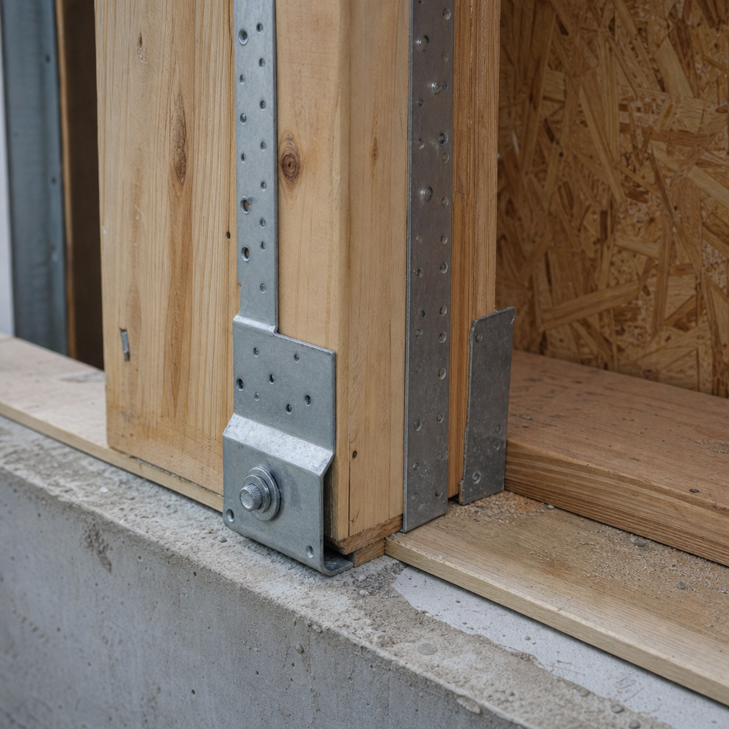
Hurricane straps and hold-downs, meticulously detailed on residential permit plan sheets, are a cornerstone of wind-resilient residential construction in Tampa, FL. Every connector, fastener schedule, and call-out directly impacts the continuous load path performance expected by the Florida Building Code (FBC) 8th Edition (2023) and enforced by Tampa’s Development Services and Construction Services departments.
Specification and Graphic Representation of Roof-to-Wall Uplift Connectors
FBC 8th Edition Wind Design and Roof Connector Requirements
The FBC 8th Edition (2023), adopted throughout Tampa, mandates that every roof assembly must have connections capable of resisting uplift dictated by wind design values. Under IRC Section R802.11, each rafter or truss-to-wall connection must resist uplift calculated for the assigned ultimate design wind speed and exposure category-a direct function of site location, structure geometry, and height. In Tampa, most projects use Exposure Category B or C and reference a wind speed of 130-140 mph (Vult) per ASCE 7-16 and Table R802.11 (legalclarity.org).
For instance, a roof rafter with a 28-ft span, spaced 24” O.C., in Exposure B at Vult 130 mph must provide connection resistance of at least 167 lbs uplift per fastener. Both the IRC Section R802.11 and IBC Section 2308.11.4 (codes.iccsafe.org) require metal connectors or engineered alternatives that create a continuous load transfer from roof to wall plates, down through bearing points to the foundation.
Connector Types, Load Ratings, and Plan-Set Representation
In practice, common connectors include Simpson Strong-Tie’s H1, H2.5A, and HGA10-all fabricated of galvanized steel and listed with their allowable uplift values:
- H1: 850 lbs allowable uplift (with full fastener schedule - 8-10d x 1.5” nails each leg)
- H2.5A: 635 lbs allowable uplift (with 6-10d x 1.5” nails)
- HGA10: 995 lbs allowable uplift with specified screws or nails
Connector dimensions, such as the H1 at 3-1/16" x 1-1/4" x 2-3/4", must be documented to allow for proper positioning on narrow top plates and against adjacent framing. Material specifications must state galvanized steel for all connections, particularly as required by code for corrosion resistance in humid/hurricane-prone areas.
Typical Drawing-Sheet Conventions and Redlines
Permit plans require clear graphic and textual representations on both roof framing plans and dedicated connector detail sheets:
- Connector Symbols/Call-Outs-Each tie location on the roof or ceiling plan must be marked (e.g., “H1 @ each rafter/truss seat”) with enlarged detail bubbles keyed to detail sheets.
- Enlarged Detail Views-Details show each connector in elevation and section, specifying required nail/screw pattern (reference: “Nail all holes, 8-10d x 1.5” nails per Simpson table” for H1).
- Connector/Fastener Schedules-A table on the structural or detail sheet spells out connector types, installation orientation, required fastener size and quantity, minimum bearings, and manufacturer product approval (NOA or ICC-ES). Example: “H2.5A: 6-10d x 1.5” nails, both sides of rafter, install tight to plate.”
- General Notes Section-Mandatory note: “All connectors to be installed per manufacturer’s instructions and as required for design wind speeds per FBC 8th Edition (2023)/ASCE 7-16.”
Tampa Development Services routinely redlines plans for missing uplift connector sizing/capacity notes, ambiguous fastener patterns, or insufficient call-outs at roof truss ends and valleys. A common comment: “Provide connector schedule with type, spacing, and load rating for all roof-to-wall connections; clarify which members require H1 vs H2.5A; list fastener requirement per location.”
Manufacturers’ Information and Code Approvals
Plan sets must cross-reference manufacturer approvals, such as the full ICC-ES Evaluation Report or Miami-Dade NOA for each specified connector-especially for hardware substitutions during construction.
Design and Documentation of Hold-Downs and Embedded Connectors for Foundation Load Transfer
Lateral and Uplift Load Requirements in Tampa Context
Transferring lateral and overturning forces into the foundation is codified in FBC Residential Section R301.1 and R602.11: “A continuous load path must be provided to transfer all loads from the roof and from lateral forces into the foundation.” Wind pressures on gable ends, shearwalls, and critical wall panels require specific hold-downs at their base-the “first link in the load path chain.”
FBC Section R403.1.6 covers anchor bolt standards: Minimum 1/2” diameter, min. 7” embedment, spaced max 6’-0” O.C., and within 12” of plate ends. These are minimums; engineered locations such as high-load shearwall ends almost always require denser bolt layouts and additional embedded connectors for wind design loads as per Table R602.11.1.
Continuous Hold-Down Hardware and Detailing on Plans
Commonly specified engineered connectors include:
- HTT (High Tension Tie) series (Simpson Strong-Tie HTT4, HTT5): For shearwall end posts and main drag struts. Example: “HTT5 hold-down at S.W. end post, 1” anchor bolt x 18” embedment, per Simpson ICC-ES ESR-1775.”
- HDU (Heavy Duty Uplift): For main wind force resisting system (MWFRS) loads where high uplift is calculated.
- STHD (Strap Tie Hold Down) series: Used for wood posts/columns at grade beams or foundation walls in narrow wall conditions.
Every hardware call-out must indicate:
- Connector Model: E.g., “Provide Simpson HTT5 (or approved equal) at all shear wall ends.”
- Bolt Size and Embedment: “1” dia. x 18” embed anchor with ASTM A307 nut and washer.”
- Reference to NOA or ICC-ES: “Install per ICC-ES ESR-1775 or Miami-Dade NOA XXXX.”
Hold-down installation details are graphically represented in plan sections through end walls, showing hardware extending from stud to anchor, along with a matching anchor bolt schedule tabulated for the entire foundation plan.
Embedded Strap Detailing for Slab-on-Grade
Strap-type hold-downs (e.g., Simpson STHD14) are often specified for slab-on-grade construction prevalent in Tampa. The detail must make clear:
- Strap orientation and length (e.g., “STHD14 strap embedded min. 12” in slab, 4” below top of concrete, installed vertical, aligned with wall stud.”)
- The required number of fasteners and their schedule: “Bracket to be nailed with 4-16d common to double stud.”
- Coating: “All embedded hardware to be hot-dip galvanized, ASTM A153, to resist corrosion per FBC Table R317.3.1.”
All such details must be drawn at an appropriate scale (1.5” = 1’-0” recommended) and referenced from the foundation plan with matching bubble numbers or letter call-outs.
Typical Plan Review Comments and Redlines
Redlines from Tampa reviewers on this topic typically ask for:
- Verification of hold-down sizing for wind uplift and overturning
- Clarification of anchor bolt patterns: “Anchor bolts not shown at all wall plates; add schedule as per FBC R403.1.6.”
- Elevation and section details showing full path from hardware to slab anchor, not just hardware to stud.
Foundation and wall schedules must directly address Tampa’s local amendments-especially any flood zone or Substantial Improvement (SI/SD) triggers as defined in Tampa Code Section 202 and FBC R322.
Multi-Story Continuous Vertical Load Path: Detailing Through Floor Systems
Requirement for Unbroken Load Path Between Stories
Continuous vertical load paths-uninterrupted transfer of wind and gravity forces from the roof apex through intermediate floors to the slab-are essential on residential structures greater than one story. FBC 8th Edition (R301, R602.3, R802.11) mandates that “all framing and connections between levels provide continuity of load path for uplift and lateral transfer.”
Interruptions at rim boards, floor trusses, or platform framing elements are the most common weak points. Tampa’s plan reviewers expect explicit demonstration, in both framing plans and cross-sections, of how the load path is maintained at each change of direction or material.
Strap Connectors (MST, MTS Series) and Through-Bolting Practices
Use of high-capacity steel straps (Simpson MST/MTS series) is standard practice at multi-story wall lines and floor edge transitions:
- MST37: 1-3/8" x 37" strap, allowable tension load 1,005 lbs with 10d nails in all holes.
- MTS12: 1-1/4" wide, for tighter stud layouts, allowable tension 575 lbs.
Straps are shown running from the top plate of lower walls up over rim joists/floor trusses to the bottom plates above. Details must display:
- Fastener schedule: “10d x 1.5” nails, fill all holes, stagger nails if needed to avoid splitting.”
- Load path hand-off: “Strap must start at double top plate, pass continuous over rim board or engineered floor edge, attach to double bottom plate above.”
- Notes for through-bolting at critical points: "Install 1/2” A307 through-bolts with 3” x 3” plate washers at uplift transfer points through rim joists and wall posts.”
Rim board connections present unique challenges, especially where engineered lumber is used. The floor framing plans must specify the rim board thickness (minimum 1-1/8” APA rated for continuous strapping), indicate “nail to rim per APA Table 2A,” and reinforce with supplemental blocking if specified loads exceed standard values.
Dedicated Cross-Section and Schedule Detailing
Multi-story load transfer details are best handled via dedicated sections-often cut through stairwells, shearwalls, or end walls-clearly showing uplift connectors installed in sequence and with continuous nailing from roof to foundation. Adjacent schedules list each floor line, the type of connectors, size, nailing, and special notes such as fireblock requirements or insulation continuity for energy code compliance.
Tampa’s plan reviewers frequently redline plans for:
- Omissions in strapping at intermediate floors (“Provide continuous strap at all end wall lines through 2nd floor diaphragm”).
- Insufficient fasteners due to switching from solid sawn to engineered rim boards (“Nailing to rim insufficient; increase fastener size or add blocking per detail.”)
In each case, the correction is explicit: details must show how and where every connector crosses or is anchored through all floor system components, addressing both gravity and uplift forces as mapped from wind load calculations.
Permit Plan-Set Organization and Standardized Wind Resistance Details in Tampa
Logical Permit Plan Set Sequence and Required Sheets
City of Tampa Construction Services requires rigid organization of residential permit document sets to support fast code review and close tracking of continuous load path details. A compliant set includes:
- Cover Sheet: Project info, codes used (“FBC 8th Edition (2023), ASCE 7-16, City of Tampa amendments”) and wind design summary ("Design wind speed Vult = 136 mph, Exposure C").
- Site and Foundation Plans: Locates all wall lines and critical wind-resisting components.
- Floor and Roof Framing Plans: Identifies all rafter/truss seats, wall lines, and connector locations.
- Dedicated Detail Sheets (e.g., S-4 “Uplift and Hold-Down Details"): All metal connectors, hardware, nailing patterns, anchor bolts detailed at large scale.
- Schedules: “Connector Schedule,” “Anchor Bolt Schedule,” “Hold-Down Schedule” listing hardware, rating, location, fastener requirement. (Example: “H1 at all roof trusses, 8-10d x 1.5”, 850 lbs uplift”).
- General Notes: “All framing and connection hardware shall comply with FBC 8th Edition and ASCE 7-16. Install all hardware per manufacturer’s ICC-ES/NOA documentation.”
Certain detail conventions are expected: Each connector uses the official hardware symbol, with a unique drawing call-out referencing the detail sheet (“see 8/S-4”). All detail sheets are cross-referenced in bubble keys, and hardware schedules are tabulated at the bottom or side of the sheet for quick inspector access in the field.
Wind Design Criteria, General Notes, and Connector Schedules
A critical distinction for Tampa permit sets is direct compliance with Code Section 1609.3.1, requiring listing of:
- Ultimate and nominal wind speeds (“Vult = 136 mph, Vasd = 105 mph”).
- Exposure Category (“Exposure C-open terrain with scattered obstructions”).
- Component and cladding pressures-tabulated by roof zone and referenced to ASCE 7-16 diagrams.
- Internal pressure coefficients, risk category, and windborne debris protection zone identification.
A standard general note appears on all plans: “Continuous load path for all wind, gravity, and lateral forces to be maintained from roof to foundation via specified connectors and uplift hardware. All connectors to be installed per schedule and per manufacturer’s latest Approval Letter/NOA/ICC-ES ESR.”
Common Redlines and Field Inspector Requests
Frequently cited plan-review redlines include:
- Omitted design wind speed values (“Revise plans to specify wind design Vult and Exposure Category as per ASCE 7-16 and FBC 8th Edition.”)
- “Missing connector schedule-add table listing all hardware by location and include allowable loads.”
- “Enlarge detail sheets to clearly indicate nailing patterns, installation direction, and required fastener quantities per device.”
- “Clarify continuous load path at second-floor rim-show strap from roof plate to foundation wall.”
Prioritizing these plan set standards reduces code resubmittal cycles and clarifies responsibilities among architects, engineers, and field crews.
Field Troubleshooting and Responding to Plan Review Redlines in Tampa
Addressing and Revising Redlines in the Permit Review Process
The City of Tampa’s digital resubmittal portal expects annotated revisions for each plan review comment, especially regarding hardware and continuous load path:
- Each redline addressed in a response letter (“Added H1 connector call-out at all truss seats. Reference symbol added to Roof Framing Sheet S-5. Connector Schedule updated.”).
- Revised sheets clearly clouded or delta-marked showing new/changed information. For example, new strap run clouded at second-floor rim, with “Rev. 2” bubble.
- Product approvals must be uploaded for all hardware substitutions. For instance, if a different hold-down is used in the field, submit the new NoA or ICC-ES approval report and clarify with a revised detail (often called out as "Field Change" on the plan set, referencing modification documentation).
Common City of Tampa plan reviewer comments related to hardware: “Provide manufacturer’s load tables and installation instructions for all specified connectors. Alternate connectors require re-approval prior to installation."
Jobsite Installation Issues and Inspector Focus Points
Inspectors in Tampa’s residential construction regularly note installation errors at framing and shear wall inspections:
- Hardware installed backwards or upside down; hardware not tight to both wood surfaces
- Fasteners missing or installed at wrong angle-inspectors measure number and placement against the plan schedule (“8-10d x 1.5” required but only 4 nails present-red tag issued”)
- Hold-downs placed on doubled blocking or with insufficient edge clearance
- Straps omitted through floors or not continuous from roof to foundation as shown on permit drawings
Inspector’s checklist typically includes reference to plan details by sheet number and schedule row, requiring the full permit set be present on-site.
Documentation of Field Modifications per FBC and City Requirements
When unexpected field conditions require deviation from approved plans, detailed field modification documentation is legally required:
- Revised partial sheet showing the updated hardware/connection, clouded for clarity, stamped by the engineer of record if changes affect structural performance.
- Product NoA or ICC-ES evaluation report for substituted connectors, stapled to the permit set and referenced in a field memo.
- Contractor log of modifications, including who authorized them and dates, included in inspection documentation for final sign-off.
All city inspectors verify the installed hardware not only matches plan call-outs, but also the fasteners, embedment, and alignment shown in manufacturer’s NOA or evaluation report attached onsite. Where substitutions have occurred, inspectors check for presence of approved field change documentation before sign-off.
Drawing-Sheet Conventions for Jobsite Clarity
To ensure install teams and inspectors alike have no ambiguity, plans must always display:
- Explicit call-outs: e.g., “Install H2.5A @ each truss to plate, 6-10d x 1.5” nails, toe-installed per detail 2/S-4.”
- Connector schedules summarizing hardware requirements at every framing location (“see Sheet S-8, Uplift Connector Schedule”).
- Hardware details scaled no less than 1-1/2” = 1’-0”, with fastening patterns flagged in bold call-outs and reference to ICC-ES/NOA on every connector call-out.
This approach ensures that in the field, with or without the presence of the design professional, plans can be interpreted by both installers and inspectors, minimizing ambiguous interpretation and costly rework.
Conclusion
Every stage of permitting, plan review, and construction in Tampa, FL requires hurricane straps and hold-downs to be specified, scheduled, and detailed with precision-tying code requirements, manufacturer capacities, and field installation realities into a direct, traceable continuous load path from roof to slab. Standardized schedules, comprehensive detail sheets, clear dimensioning, and prompt, code-literate responses to plan review redlines are not only best practice, but necessary for compliance and safety in the region’s high-wind, hurricane-prone context. For professional permit plan sets or renovation documentation that stand up to Tampa’s most rigorous code and inspection environments, Kingsway Drafting & Design provides the technical expertise and drawing precision demanded by the FBC and local authorities.