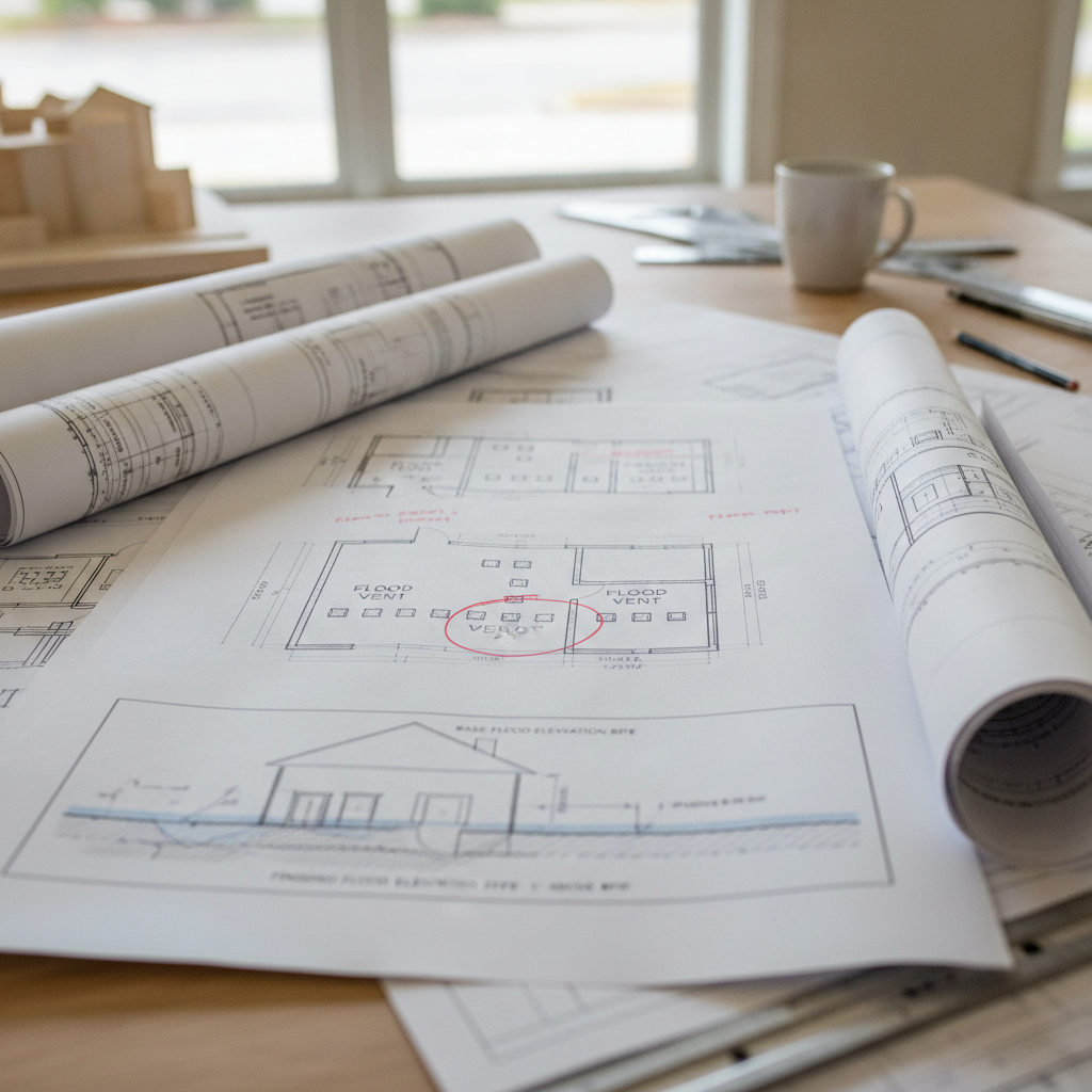
Houston’s residential development standards in flood-prone areas are rigorous and highly specific, reflecting both the evolving International Residential Code (IRC) and the City’s stringent local amendments. The details of how Finished Floor Elevations (FFE) and flood vents are depicted, dimensioned, and called out on permit drawings can dictate both permit approval and long-term code compliance. From the drafting table to the final inspection, a command of code call-outs, detail conventions, dimensioning techniques, and required documentation is paramount to ensuring both city and FEMA compliance. Each plan set must satisfy Houston’s adopted 2021 IRC/IBC, Chapter 19 of the City’s Code of Ordinances, and the city’s unique standards on freeboard, openings, materials, and workflow.
Detailing Finished Floor Elevation (FFE) on Site and Foundation Plans: Houston’s 2021 IRC/IBC 2-foot Freeboard Amendment, BFE Integration, and Dimensioning Techniques for Permit Approval
Houston’s Adopted Codes and Local Amendments
Houston officially adopted the 2021 edition of the International Residential Code (IRC) and International Building Code (IBC), with significant local amendments that raise the bar for flood protection beyond base national standards. Under the 2021 IRC, Section R322, residential projects in flood-prone areas must elevate the lowest floor above specified flood heights. The key Houston local amendment, codified in Chapter 19 of the City Code, requires new construction to elevate the FFE at least two feet above the 500-year floodplain (source), rather than just above the 100-year flood (the BFE), as is standard elsewhere.
How BFE and Freeboard Are Integrated on Houston Plan Sheets
Houston’s site and foundation plans must clearly depict both floodplain boundaries and elevation benchmarks:
- Floodplain Boundaries: Clearly delineate both the 100-year and 500-year floodplain per current FEMA panels (FIRM) and local overlays.
- Base Flood Elevation (BFE): Explicitly annotate the BFE on the site plan and foundation plan, referencing the relevant benchmark or NAVD datum.
- Finished Floor Elevation (FFE): Specify the proposed FFE, demonstrated to be at least 2' higher than the 500-year floodplain elevation.
This information must be dimensioned with reference to a known benchmark or city datum-common practice is to provide call-outs such as “FFE = 60.20' NAVD88 (2' above 500-yr BFE)” directly on plan views and foundation sections.
Dimensioning Techniques and Section Detailing
- Elevation Call-Outs: Use consistent, unambiguous symbols when labeling BFE and FFE. Elevation bubbles, leader notes, or boxed callouts are standard. For example: “BFE = 58.20' NAVD88; Proposed FFE = 60.20' NAVD88 (per City of Houston Ch 19 Amendments).”
- Benchmark Referencing: All plan elevation references must tie back to city benchmarks or established survey datum. "All elevations referenced to City of Houston benchmark 342-16, NAVD88, per Elevation Certificate."
- Sectional Cuts: On cross-sections, graphically show the ground, BFE line, and FFE offset with labeled distances. Example section cut note: “Min. 24" freeboard above 500-yr BFE per City of Houston Ord. Ch. 19-166.”
- Drainage Arrows & Slopes: Surface drainage patterns are shown with arrows, annotated to indicate slopes (2% minimum for the first 10').
These drafting conventions not only communicate compliance but anticipate concerns from city plan reviewers and on-site inspectors.
Typical Plan-Review Comments and Redlines
Plan review staff at the Houston Permitting Center critically review elevation data and documentation. Common redlines include:
- “FFE must be at least two feet above the highest adjacent 500-yr BFE on site-revise elevations and provide benchmark reference.”
- “Floodplain boundaries missing-add flood hazard overlays to site plan in accordance with FEMA panel XXXX.”
- “Show positive drainage away from structure; provide grade arrows and labeled slopes at all sides per IRC R401.3.”
Proactive drafters address these at initial submittal by including BFE/FFE tables, explicit benchmark citations, and concise drainage design notes.
Dimension and Material Specifications: What Inspectors Look For
- FFE Height: Minimum 2 feet (24") above the 500-yr floodplain as established by the most recent FEMA FIRM and Chapter 19 local data.
- Ground Slopes: IRC/IBC require a 2% slope away from the foundation for the first 10 feet (1/4" per foot).
- Foundation Materials: Any material used below the FFE is subject to flood-resistance requirements-concrete, pressure-treated wood, and closed-cell foam are accepted; drywall, standard batt insulation, and untreated wood are not.
These dimensions are explicitly annotated on foundation sections and details-non-compliance directly triggers plan review rejection or jobsite correction notices.
Key Drawing-Sheet Details: Example Call-outs
- Site Plan Keynote: “FFE = 60.20' NAVD88; Benchmark per Elev Cert #23-2372; 2' above 500-yr BFE 58.20' per FEMA Panel 48201C0720L.”
- Section Mark: “BFE (500-yr) = 58.20'-Min. FFE = 60.20' per Ch 19. Provide positive grade min. 2% (1/4”/ft) for 10’ from all walls.”
Comprehensive Flood Vent Detailing: Calculating Net Free Area per 2021 IRC R322, Specifying Engineered vs. Non-Engineered Openings, and Locating Vents on Houston Residential Foundation Plans
Flood Vent Requirements: Prescriptive & Engineered
Flood vent sizing and placement are vital in all Houston homes with enclosed space below design flood elevation (DFE), especially pier-and-beam structures and raised slabs with enclosed crawlspaces or storage. Based on IRC 2021 Section R322.2.2 and corresponding Houston amendments, the requirements are:
- Net Free Area: For non-engineered openings, provide a total net area of openings (excluding screens, louvers, etc.) no less than 1 square inch per square foot of enclosed area. Example: For 800 sqft enclosed crawlspace, provide at least 800 sq in (5.56 sqft) net opening area.
- Engineered Openings: If using engineered flood vents, provide product documentation (ICC-ES or similar) and designer’s compliance statement referencing ASCE 24 criteria. Document the designed equivalent venting and attach the manufacturer’s cut sheet.
Placement and Mounting-Houston’s Additional Mandates
The local code overlays and 2021 IRC Section R322.2.2.1 specify:
- Number/Location: At least two vents, placed on different sides of each enclosed area below BFE.
- Height: Bottom of each opening must be no higher than 1 foot above adjacent exterior/interior grade below each vent.
- Size: Each opening (after all louvers/screens) must be at least 3” in any direction.
- Exterior Exposure: All vents must be permanently open or equipped with automatic operation that does not require human intervention.
These dimensions are checked during both plan review and field inspection. Drawing conventions require vents to be clearly dimensioned, with areas either tabulated or called out directly: “(4) 8x16” flood vents @ 2 per side = 512 sq in net area; required: 500 sq in, provided: 512 sq in.”
Foundation Plan Detailing and Sheet Call-Outs
- Flood Vent Schedule: List size, type, location, total net area, product number (if engineered).
- Foundation/Elevation Views: Show precise vent locations on the exterior foundation walls and document the distance from grade to bottom of opening.
- Sectional Details: Include a wall section through a typical vent, annotated with dimensions (height above grade, vent area), construction details (material, fastening), and call-out: “Install per IRC R322.2.2; see schedule for net opening area.”
Plan reviewers expect both a table of calculations and graphic proof of vent code compliance. If engineered vents are used, a note such as: “Engineered flood vents by SmartVent, ICC ESR-2074, 7x16" each, net 200 sq in/vent per ICC report. See submittal for certification.”
Common Redlines and Field Corrections
- “Flood vent total area insufficient for enclosed space-revise vent schedule/calculations.”
- “Vents not placed on different walls as required by local amendment; revise plan.”
- “Bottom of vent elevation exceeds 12” above highest adjacent grade-relocate as required per R322.2.2.1.”
During field inspection, inspectors use a tape at vents to confirm less than one foot above grade. Call-outs, both on section and plan, such as “min/max vent elevation above grade: 0"-12"” serve as clear compliance documentation.
Material Specifications and FEMA Technical Bulletins
Flood vent components must be fabricated from flood-damage-resistant materials per FEMA TB-2: stainless steel, aluminum, or pressure-treated wood frames; screen/mesh must allow automatic flow, not impede debris egress. Sample note: “Flood vent frames: 6061 aluminum, powder-coated; screening: 1/4" stainless mesh; all hardware corrosion-resistant per FEMA TB-2 and Ch 19 Houston.”
Structural and Material Detailing for Flood-Resistant Foundations in Houston’s Flood Zones: Pier & Beam, Elevated Slab-on-Grade, Breakaway Walls, and Flood-Damage-Resistant Materials Below BFE
Pier-and-Beam Foundations: The Mandated Standard
In Houston’s mapped 100-year floodplain zones, the city’s Chapter 19 Floodplain Ordinance strictly prohibits slab-on-grade structures. Instead, residential construction must use elevated pier-and-beam foundations with these required parameters:
- Elevation of Structural Members: “The bottom of the lowest horizontal structural member supporting the lowest floor shall be elevated no lower than 18 inches above the BFE.” (Cited from City of Houston Ch 19, adopted 2021)
- Flood-Damage-Resistant Materials: All construction materials below the required FFE must comply with FEMA TB-2 and ASCE 24. Typical call-out: “All framing below BFE to be pressure-treated SYP, AWPA U1 UC4A; all blocking/concrete footings 3,000 psi min. per TB-2.”
- Anchoring: “Foundation piers to be embedded min. 24" below finished grade; anchor bolts (1/2" galvanized @ 48" OC) set in top 8" of pier.”
Pier details are shown in enlarged plans and sections, with elevations called out and materials labeled in schedule and general notes.
Elevated Slab-on-Grade Systems
While conventional slab-on-grade is generally not permitted within mapped flood hazard areas in Houston, elevated slabs (using stem walls or fill) may be considered if all flood design requirements are met:
- Elevation: Top of finished slab must be at or above Houston’s freeboard requirement (2-ft over 500-year BFE).
- Fill/Compaction: Fill must be engineered and compacted to resist scour/erosion; stem walls designed to resist hydrostatic forces.
- Flood Openings: Enclosed space created under slab must meet all flood venting requirements of IRC R322.2.2.
Detailing should include cross-sections showing the elevated stem wall, compacted fill, slab reinforcement, and drainage provisions. Notes must specify concrete mix (3,000 psi min.), vapor retarders, and compaction methods. Mechanical/electrical stub-ups through slabs must occur only above required finished elevation.
Breakaway Walls Below FFE
Any enclosures below BFE used for parking, access, or storage must use “breakaway” (frangible) walls, designed to fail without jeopardizing structure. 44 CFR 60.3(e)(5) and IRC R322 require:
- Design Load: Walls to break away at loads between 10-20 psf.
- Material: Use lightweight, nonstructural materials-pressure-treated wood with corrosion-resistant fasteners, open lattice, or removable infill.
- Attachment: Connection details should show nailing patterns, sheathing thickness, and a call-out: “Breakaway wall-1x4 PT lumber at 24" OC nailed w/ 8d at 16" OC; attach to joists/min restriction at 10-20 psf; not part of lateral load path.”
Call-out in architectural details: “Enclosure below BFE constructed w/ breakaway wall per IRC R322.2.5, designed for 10-20 psf, to be used for parking or storage only.”
Flood-Damage-Resistant Materials: Detailing and Specifications
- Acceptable: All concrete (cast, block), closed-cell rigid foam insulation, pressure-treated grounds and framing, structural steel with epoxy or HDG coating, non-paper-faced tile backer.
- Unacceptable: Standard gypsum drywall, batt insulation, OSB, untreated woods, carpet, porous plastic.
Material schedules specify FEMA TB-2 classification (Class 4 or 5) for below-BFE installations. Example: “Crawlspace floor: 4" slab, 3,000 psi, vapor retarder, Class 4 moisture resistance. Walls: CMU, filled, waterproofed outside, parge coat inside.” General note: “No absorptive materials permitted below DFE per IRC R322.1.8 and FEMA TB-2.”
Common Plan Review and Field Comments
- “Slab-on-grade foundation not permitted in mapped floodplain-revise to pier-and-beam system per Chapter 19.”
- “Materials below BFE not specified or not flood-rated-provide FEMA TB-2 compliance in finish schedule.”
- “Breakaway wall details missing load calculation-add section and PSF note for all walls below BFE.”
Clouding of revised details and adding narrative notes referencing code sections (e.g., “See Ch19-85, IRC R322.2.5”) expedite re-review and minimize permit delays.
Navigating the City of Houston P&D Permit Workflow: Required Flood Zone Submittals, Common Redlines for FFE and Flood Vents, and Responding to Plan Review Comments on Permit Drawings
Required Flood Zone Permit Submittals
- Elevation Certificates: Per City guidelines, surveyor- or engineer-signed ECs must be submitted at three stages: initial plan review, pre-framing inspection, and final inspection.
- Flood Mitigation/Drainage Plan: Identify no-net-loss of flood storage by shading cut/fill, provide finished grades, and address site access.
- Site Topographic Survey: Required showing existing/proposed contours, BFE, and benchmarks.
- FFE Call-out: All slabs and floors labeled with elevation to 0.01-foot precision, referenced to the elevation certificate and benchmark.
- MEP Equipment Elevations: “All mechanical/heating/cooling/plumbing fixtures to be elevated min. 2’ above 500-yr BFE as per Ch 19, Sec. 32a(4).”
Submittals with missing or unclear elevation data, benchmarks without description, or incomplete ECs frequently result in returned plans without review.
Typical Redlines for FFE and Flood Vents
- FFE below required minimum: “Revise slab elevation to 2’ above 500-yr BFE. Provide updated site and foundation plan.”
- Flood vent area misunderstandings: “Vent calculations must show total net open area; specify dimension and location of each vent on all sides.”
- Incomplete vent detail: “Add wall section at flood vent showing elevation above grade; label vent as ‘automatic’ or note ‘permanently open’.”
Responding with revised details and explicit tables (“Flood openings-Provided: 854 sq in; Required: 800 sq in. See vent schedule.”) avoids further cycles of rejection.
Responding to Plan Review Comments: Sheet-by-Sheet Best Practice
- Documentation: Cloud all revisions and re-date each affected sheet. Respond to each comment in a plan review response letter, referencing sheet and detail numbers: “Comment #3: FFE raised on sheets A1.1, F1.0 per Ch19.”
- Sheet Call-out Consistency: Ensure elevation notes and vent details are coordinated between site, foundation, and section sheets. Redundancy prevents field confusion and final inspection delays.
- Legible Benchmark References: Call out surveyed datum in every relevant sheet and section.
- Code Reference Tables: Tables listing all elevations, benchmarks, BFE, and FFE, and associated code sections, preempt code compliance disputes on both plans and in the field.
Key Specs and Drawing Conventions for Houston Workflow
- Flood Vents: “Provide (3) 8"x16" flood vents @ base of south, east, and west foundation walls, bottom 8" above grade, for 768 sq in net area (required: 720 sq in).”
- FFE Verification: “FFE = 62.10’ NAVD88; BFE = 60.10’. Surveyed at rough-in and prior to C/O.”
- Mechanical System Elevations: “Outdoor condenser to be mounted on raised platform at 64.10’ NAVD88 (≥2’ above 500-yr BFE).”
Reviewers regularly check that all critical call-outs match EC submissions, and that every plan view and section consistently identifies required elevations in relation to City benchmarks.
Post-Permit Compliance and Jobsite Verification: Ensuring FFE Accuracy, Proper Flood Vent Installation, and Documentation (Elevation Certificates) for City of Houston Inspections and FEMA Compliance
FFE Field Verification and Documentation
After permit issuance, the as-built FFE must be documented and verified on-site, with elevation certificates provided at framing and final inspections. City inspectors require:
- Survey Benchmarks: Temporary benchmarks transferred from original permit plans must be preserved, visible, and reference-able on site.
- Elevation Confirmation: Measurement to the hundredth foot at threshold, compared against EC and permitted FFE. Common inspection note: “FFE field measured 62.14’, matches EC; OK to proceed.”
Inspector redline if deviation found: “FFE as built at 61.82’-must raise to match permitted FFE 62.10' per EC or re-permit with floodplain office.”
Flood Vent Installation: Field Checks
- Location and Area: Inspectors measure vent opening size, confirm at least two on separate exterior walls, check area calculation against the enclosure square footage.
- Elevation: Confirm bottom of each vent less than one foot above exterior grade.
- Field note: “West wall vent bottom at 0.82’ above grade-compliant.”
- Correction: “South wall vent at 1.18’-rejection; must be lowered per IRC R322.2.2.1.”
- Materials and Operation: Vents must be corrosion-resistant, unobstructed, and either always open or open automatically.
Site plan and elevation sheets should mark “V” symbols keyed to schedule; field inspector cross-references to check that installation matches plan location, count, and area.
Elevation Certificates: Submissions, Corrections, and As-Built Documentation
- Submission Stages: FEMA Elevation Certificate required at plan review (proposed), pre-framing (under construction), and at final (as-built).
- Data Requirements: Must show:
- Lowest floor elevation (including basement/crawl if any)
- Lowest adjacent grade
- BFE at site
- All benchmarks, including description and datum (typically NAVD88)
- Certification: Prepared, signed, and sealed by a licensed land surveyor, engineer, or architect. Errors, omissions, or inconsistent data between site and EC are rejection triggers.
Plans should call out: “All FFE, BFE, and benchmarks indicated per Elevation Certificate #12345, Survey by TXPLS #9876, dated [MM/DD/YYYY].” On-site benchmarks must align with those in submitted EC for seamless compliance at inspection.
Final Inspections and FEMA Compliance for Insurance and Certificate of Occupancy
- Documentation Presented: As-built EC, updated vent area calculations (if changed during construction), revised site plan if grading/FEE shifted.
- Inspector Actions: Walk through with EC; verify actual conditions against plans and EC; reference code section per Houston Ch 19, IRC R322, and inspection checklists.
- FEMA Compliance: Only upon documentation of full compliance with floodplain elevation and venting standards is the final inspection signed off-ensuring lowest possible NFIP insurance rates for property and eligibility for Certificate of Occupancy.
Discrepancies on elevations or venting observed at inspections require correction before occupancy is granted.
Conclusion
Every stage, from initial drafting of Houston residential permit drawings to as-built field verification, demands meticulous attention to FFE and flood vent detail: precise dimensional call-outs, code-referenced benchmarks, thorough EC integration, and field-verified compliance with all city and FEMA mandates. Familiarity with local amendments, standard plan review comments, and field inspection routines enables drawings that move efficiently through permit review and pass all field checks-protecting property, accelerating schedules, and ensuring full compliance with both city and federal requirements. Kingsway Drafting & Design provides these details expertly for every Houston-area project.