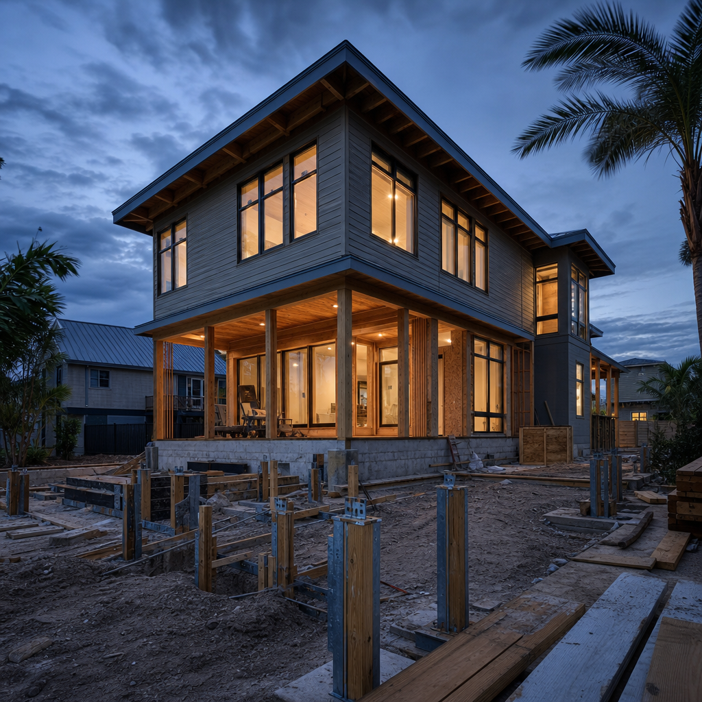
Wind-resistant shear wall hold-down specification and anchorage detailing on Florida residential architectural drawings must precisely address the Florida Building Code (FBC) 8th Edition (2023), City of Tampa review conventions, and the realities of slab-on-grade construction, especially given Tampa’s ASCE 7-22 wind design requirements. Construction document completeness, dimension accuracy, and the clarity of code call-outs directly determine the likelihood of first-cycle permit approval and jobsite compliance.
FBC 8th Ed. (2023) Shear Wall Schedules and Hold-Down Device Specification on Structural Sheets for Tampa's Wind Design Criteria
Wind Load Calculation and Code Section Referencing
Florida Building Code, Residential Section R301.2.1.1 enforces that wind loads conform to the provisions and methodology of ASCE 7-22, which establishes the wind map zones and load assumptions for all new wood-framed buildings in Tampa. Design wind speeds for the City of Tampa typically reference ultimate wind speed of approximately 140-150 mph, Exposure B or C, depending on site, and Risk Category II for single-family detached dwellings. These criteria must be listed prominently on the first or second structural page, typically under a “General Structural Notes” or “Wind Design Criteria” header-including wind speed, exposure category, risk category, and the governing load code (“Designed for 150 mph ultimate wind speed per ASCE 7-22, Exposure C, Risk Cat II”).
Under IBC Section 1609 and FBC correlates, wood shear walls and their anchorage are elements of the main windforce-resisting system (MWFRS), and shear wall schedules must be provided for all residential permit sets in Tampa.
City of Tampa Amendments and Plan-Review Triggers
Tampa’s application of the FBC incorporates technical amendments for local wind speeds, flood criteria (when relevant), and prescriptive versus engineered bracing solutions. Tampa Construction Services references the same FBC edition as the state, but plan reviewers may request:
- Supplemental statements that the plans conform to “all applicable local amendments to the 2023 FBC.”
- Identification of the zoning district (e.g., RS-50, RM-16) that might trigger additional wind exposure or setback requirements for homes in defined overlays or floodplains.
- Justification of wall bracing choices or wind design assumptions beyond SSTD 10-99 or Table R602.10.x if alternate methods are used.
Frequent comment examples include:
- “Provide wind load calculations and clarify wind speed and exposure category. Show braced wall lines and identify wall panels designed for wind resistance.”
- “Show shear wall schedule and provide details for hold-downs at wall endpoints. All structural details to reference current FBC edition.”
Drawings, Schedules, and Specification Conventions
Tampa expects structural plan sheets (often “S1,” “S2,” etc.) to contain detailed tabular Shear Wall Schedules cross-referenced to architectural plans. Each shear wall row addresses:
- Panel location (Grid A/1, etc.) and identification
- Wall length and height
- Sheathing type (e.g., “7/16” OSB or 1/2” Plywood APA Rated Sheathing”)
- Edge and field nailing pattern (“6” o.c. edge, 12” o.c. field-per Table R602.3(1)”)
- Stud type/spacing (“2x6 #2 SYP @ 16” o.c.”)
- Required hold-down or anchorage device by reference (see “HD-1” in Hardware Schedule)
A separate Hold-Down Device Schedule expands these references: “HD-1 = Simpson Strong-Tie HDU2-SDS2; Anchor: 5/8” Ø x 12” L A.B., 8” min. embedment; Capacity: 3290 lbs; Install per manufacturers’ ICC ESR #1056.” Schedule columns document:
- Device symbol
- Manufacturer/model, ICC or Florida Product Approval number
- Minimum tension (uplift) capacity
- Required anchor bolt size and embedment
- Installation notes (“Washers required under nut; hardware hot-dip galvanized per FBC Table R317.3.1”)
Drawing-sheet call-outs (found in plan view, enlarged details, and wall sections) reference both the unique wall or hardware symbol and the schedule: for example, a plan callout reading “See S2/4, Sched. ‘HD-2’”.
Per FBC Section R602.11, the minimum size hold-down anchors for wind bracing typically is 1/2” or 5/8” anchor bolts, 7”-12” embedment based on uplift calculations. Additional notes should call out washer diameter, nut tightening, and material corrosion requirements.
The wind design criteria block, shear wall schedule, hold-down schedule, and schedule references on plans form the core documentation for plan reviewers and jobsite verification alike.
Dimensioning and Detailing Hold-Down-to-Foundation Anchorage on Foundation Plans and Wall Sections for Tampa's Typical Slab-on-Grade Construction
Prescriptive and Engineered Anchorage Requirements
Most Tampa residential foundations use slab-on-grade with integral thickened edge beams ("turned-down slabs"), requiring full anchor bolt plans as governed by FBC Section R403.1.6. This section prescribes:
- “Wood sole plates at all exterior walls… shall be anchored to the foundation with minimum 1/2” diameter anchor bolts spaced a maximum of 6 feet on center. Bolts shall extend at least 7” into concrete…”
- “There shall be a minimum of two bolts per plate section, with one bolt located within 12 inches of each end of the plate section.”
For engineered shear wall hold-downs (where uplift loads exceed prescriptive limits), use of proprietary connectors (Simpson, MiTek, USP) is required, coordinated with structural engineer’s calculations.
Standard Sheet Call-Outs for Anchorage
On foundation plans (“S1”), anchor bolt layout is shown explicitly-at every hold-down, the plan should indicate:
- “5/8” Ø anchor bolt, 12” embed., 4” from end of plate, w/ 2” HDG sq. washer, typ. @ hold-downs”
- “1/2” Ø anchor bolts @ 6’-0” o.c. between hold-downs, 7” min. embedment”
Base of wall details (“S2/3” or “2/S4”) must be referenced by bubble from the foundation plan and should clearly show:
- Footing depth and width (e.g., “12” x 24” thickened edge at shear wall-see FDN Sch.”)
- Location of “HD-1” or specified hold-down:
- “Simpson HDU2-SDS2, per Hardware Schedule, attached w/ (1) 5/8” Ø A.B., 12” embedment, located adjacent to wall stud. Provide 2” sq. washer, tighten per manufacturer.”
- “Reinforcing: Provide (2) #5 horiz. bars continuous at slab edge. Maintain 2” min. clearance around all hold-down anchors.”
For floodplain overlays, notes must address “Foundations to be designed for flood loads per FBC Chapter 16 and local amendments.” Slab elevation and waterproofing details may also be required for lots within Special Flood Hazard Areas (SFHAs).
Common Redline Triggers and Corrections
Tampa plan reviewers routinely mark plans for:
- Omitted or unclear anchor bolt and hold-down spacing (“Clarify bolt spacing at shear wall hold-downs and at intermediate locations.”)
- No manufacturer/model or tension value for specified connectors (“Specify ICC-ESR and Florida Product Approval number for hold-down hardware.”)
- Missing section cuts or omitted details for transitions between wall hold-down anchor, slab edge, and reinforcement (“Add section showing connection of HD-2 to turned-down slab. Clarify min. embed and washer size.”)
Jobsite corrections commonly result from misinterpreted call-outs (e.g., anchor installed off-alignment with stud, or not at the edge of wall per plan bubble), or from missing documentation to support non-prescriptive installations.
Coordinated Detailing of Shear Wall Openings, Collector Elements, and Hold-Down Conflicts in Residential Zoning Districts within City of Tampa Jurisdiction
Governing Code Provisions and Local Zoning Table References
Configuring a wind-resisting plan becomes most complex when shear walls include openings (windows/doors), when collector elements must drag or distribute lateral loads across discontinuities, and where hold-downs must align both with the actual field framing and with plan zoning overlays (e.g., RS-50 lots with high exposure, or “RM-16” where lot width triggers additional bracing).
FBC Residential Section R602.10:
- All braced wall lines must be identified. “Braced wall lines shall be straight lines through the building plan…”
- Section R602.10.4 specifies that “Openings in braced wall panels shall be permitted provided the sum of the widths of all openings does not exceed 50 percent of the length of the braced wall panel.”
- “Where wind loads require, anchors or hold-down devices shall be provided at each end of the braced wall panel.”
FBC Building 2305.1-2305.2, Collector/Drag Elements: Load path continuity “shall be provided from each braced wall panel across openings via collector (drag) members of sufficient size and anchorage to carry forces to the shear wall system.”
Documenting Openings and Load Path Coordination
Shear wall plans (S1 and S2) must:
- Show every opening in a braced wall with window/door call-outs (“(4) 3060 Win. @ Shear Wall SW-2”).
- Provide enlarged framing details, section bubbles (“4/S5”), for panels with openings, showing king, jack, and header size (“(2) 2x6 king + 1 jack stud per end; (1) 2x8 header for 3060 opening at SW-2”).
- Apply plan notes: “Reinforce panel at window per 4/S5. Collector 2x8 SYP above and below header to drag shear loads per FBC 2305.2.”
Collector elements are dashed or shaded “drag struts” with directional arrows and bubble references to connection details (e.g., “Drag Strap per det. 7/S6; CS16, fasten both ends w/ (6) SDS 1/4” screws to collector + shear wall stud”).
Conflict points-where hold-downs clash with window/door locations-must be resolved on the plans, never by field “fixes”:
- “Hold-down ‘HD-2’ offset 10” from stud at opening-provide revised detail, verify edge distance per manufacturer.”
- “Conflict: Door swing at hold-down. Shift hold-down to adjacent stud and connect with double top/bottom plate collector, see 5/S8.”
Redline Scenarios and Reviewer Requests
Tampa plan review will redline:
- “Provide calculations demonstrating that the proposed openings in shear walls comply with FBC R602.10.4.”
- “Clarify collector elements at braced wall panels with openings. Detail connections to adjacent wall segments.”
- “Hold-down at window interferes with sash access: relocate per engineering, revise detail on S4.”
Each such comment is addressed by:
- Dimensioned framing plan overlays
- Section details at >1½″=1′ scale for connection/collector conflicts
- Schedule cross-references so every unusual anchorage is directly tied to the appropriate bracket, strap, or drag member, with code-compliant fastener schedules noted (“Simpson CS16, Florida Product Approval #FL12345, Uplift 4500 lbs, 6-SDS screws per end”).
Incorporating 'Special Inspection' and Field Verification Notes for Shear Wall Hold-Downs on Plan Sets Submitted to City of Tampa Permitting
IBC 1705 Special Inspection Trigger Language and Drawing-Sheet Inclusion
IBC Section 1705.12.1 (and referenced in FBC and City of Tampa amendments) mandates periodic special inspections for the installation of nailing, bolting, anchoring, and other fastening of components that are part of the windforce-resisting system. Although single-family dwellings (IRC) sometimes are exempt, City of Tampa reviewers do request inspection call-outs for the following (especially on higher-value projects or those in a Flood Hazard Area per City zoning):
- All hold-down anchor installations at shear walls with uplift/load capacity exceeding prescriptive.
- Hold-down-to-foundation connections (pre-pour and post-install).
- Specialty connectors, high-load transfer strapping, or wood-to-concrete “moment” connections critical to the lateral load path.
Best practice on drawings: “General Structural Note G-8: The installation of all structural hold-down connectors, anchors, and shear wall nailing shall be subject to special inspection by an approved third party per FBC 1705.12.1 and City of Tampa amendments. Contractor shall notify engineer of record prior to concealment of hardware.”
Each detail involving proprietary hold-downs should bear a bubble or cloud labeled “Special Inspection Required Per Note G-8” (or similar). Structural schedules should indicate in a dedicated column “Special Inspection: YES/NO,” making it clear to reviewers and inspectors which hardware installations fall under this requirement.
Reviewer Redline Patterns and Counter-Examples
Common City of Tampa comments:
- “Include a note requiring special inspection for wind-resisting anchors and hardware.”
- “Clarify field verification to be completed prior to concealment at critical hold-down anchors.”
- “General notes must specify code section for special inspection-reference FBC 1705.12.1.”
Omission of these notes leads to re-review cycles and inspection confusion. Inclusion and sheet cross-referencing virtually guarantees clearance of this code issue at plan review and simplifies jobsite sign-off.
Installation, Inspection, and Documentation
Drawings must support:
- Photographic and written installation records at each special-inspected connection (“Record photo and torque value of anchor nut at HD-2 installed at S2/6 location”).
- Field checkboxes on schedules (“Inspector initials/date - hardware installed and verified per FBC 1705.12.1”).
Schedules and call-outs must align so the special inspector, building official, and contractor can all correlate what was installed against what was documented.
Troubleshooting Common Hold-Down Redlines from City of Tampa Plan Reviewers and Jobsite Corrections for Detailing Errors
Redline Categories and Standard Solutions
City of Tampa plan reviewers repeatedly redline and request detail revision in several predictable ways:
- Missing/Incomplete Fastening Schedules: “Provide a complete fastening schedule for wall/roof/joint connections.” Schedules must explicitly tabulate all hold-down connectors, their model/part number, exact required fasteners (“6-SDS 1/4” screws per Simpson table”), and applied spacing. A simple “See manufacturer” note is insufficient.
- No Uplift Values: “No uplift values shown for specific connections.” Each shear wall and hold-down detail must reference the calculated demand and the provided capacity, either in a schedule row or an inline note (“HD-3 provided Uplift: 3900 lbs; Demand: 3720 lbs per calc sheet S7”).
- Insufficient Connector Details (Proprietary): “Proprietary connector details lack ESR number or capacity documentation.” Each non-generic (Simpson, MiTek, USP) connector must include its ICC ESR number or Florida Product Approval number and tabulated load capacity.
Drawing-Sheet Detail Conventions for Approval
- Detail Orientation and Length: Call out hardware orientation and embedment: “STHD14 strap embedded min. 12” in slab, aligned with wall stud, installed vertical, 4” below top of concrete.”
- Fastener Schedule: “Strap to be fastened with (4) 16d common to stud, (2) 16d to top plate. All per manufacturer.”
- Material Coating: “All embedded hardware to be hot-dip galvanized, ASTM A153, to resist corrosion per FBC Table R317.3.1.”
- Drawing Scale and Bubble Call-Outs: Details at large enough scale for field verification (≥1.5″=1′-0″), with matching reference bubbles from foundation and shear wall plans, “See Det. 3/S4.”
Field Corrections, Jobsite Review, and As-Built Revision
Common jobsite errors that become stop-work issues at inspection include:
- Misaligned hold-downs/anchors due to misunderstood plan bubble (“Installed HD-2 12” off from scheduled gridline; inspector red-tagged for non-compliance; must sawcut and re-anchor per revised S4 detail”).
- Anchors/straps without full fastener quantity ("Observed only 2 of 4 required 16d nails-correct per schedule, re-inspect per structural sheet S7").
- Material substitutions without documentation ("Builder installed USP connector instead of Simpson; inspector requires new calculations, Florida Product Approval & manufacturer's install sheet").
- Uninspected concealment ("Covered hold-down prior to inspector photo-must remove finishes, re-inspect at cost").
Solutions always track back to documented, cross-referenced details and schedules, clear general notes (including special inspection reference), direct code citations, and full capacity documentation per city requirements.
Conclusion
Tampa’s enforcement of FBC 8th Edition (2023) and its plan review culture demand a precise architectural drafting approach to shear wall hold-downs and anchorage, centering on tabular schedules, dimensioned details, code-cited general notes, special inspection cross-references, and manufacturer load data. Every phase-from drawing-sheet layout to plan review response to field inspection-relies on document clarity, code tie-back, and schedule-to-detail traceability to avoid cycles of redlines or jobsite corrections. Projects that rigorously follow these conventions pass review and inspection with minimal friction, ensuring structures are both code-compliant and resilient amid Tampa’s wind-driven reality.
Kingsway Drafting & Design specializes in creating detail-rich, code-aligned construction documents tailored to Tampa’s stringent structural review standards.