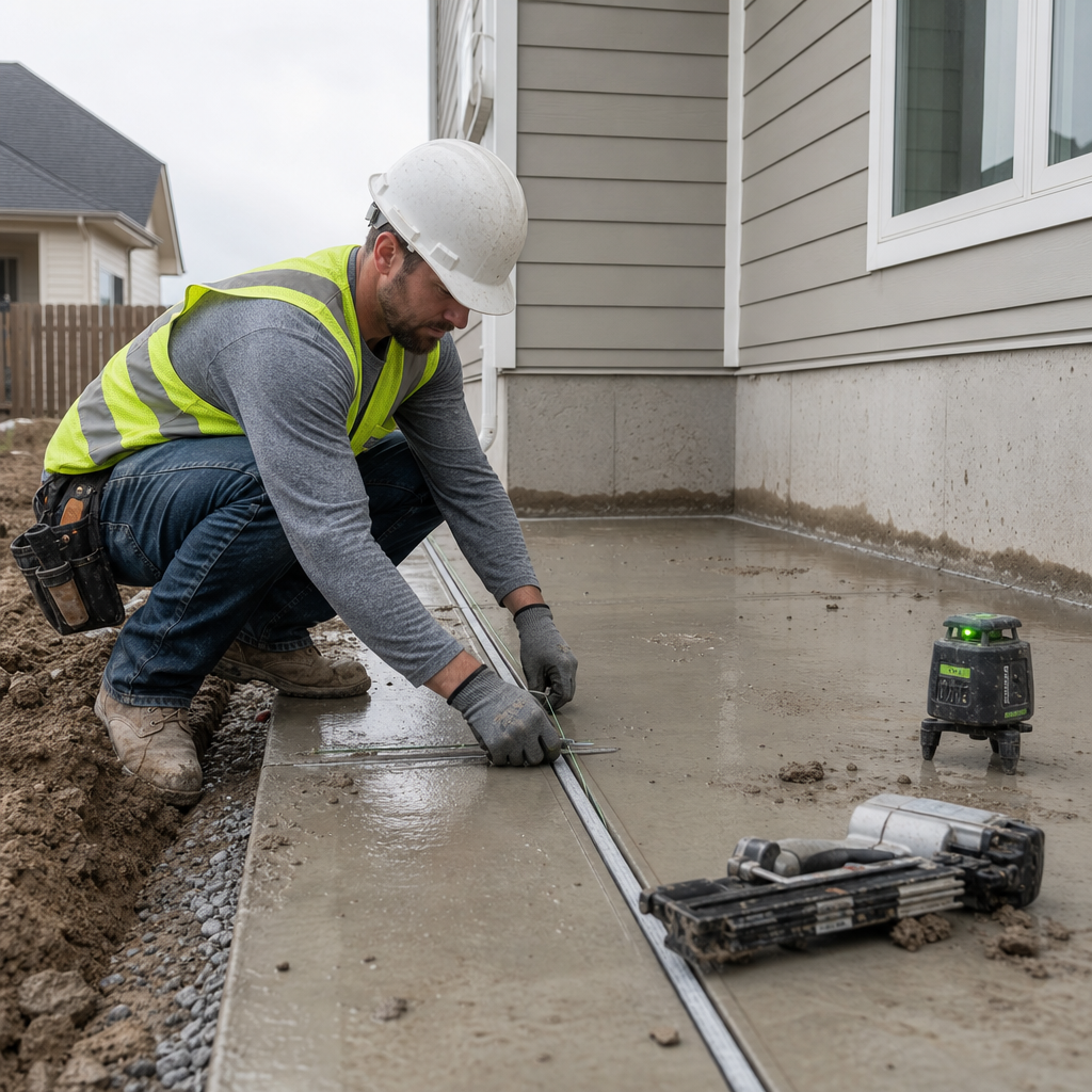
Full-depth isolation joints between exterior concrete flatwork and residential foundations are not merely a graphic on a plan sheet in Houston, TX-they are a code-mandated detail requiring precise specification, dimensioning, and documentation due to the city’s unique climate and active soils.
IRC 2018 (Houston Amendments) Compliant Isolation Joint Detailing for Exterior Flatwork Abutting Foundations
Code Sections and Houston Amendments: R401.3 and R403.1.1
Houston enforces the 2018 International Residential Code (IRC 2018) as locally amended, centering isolation joint requirements at the intersection of two key code mandates:
- IRC R401.3: Drainage-“Lots shall be graded to drain surface water away from foundation walls. The grade shall fall a minimum of 6 inches (152 mm) within the first 10 feet (3048 mm).” In exterior concrete flatwork, isolation joints play a crucial role by allowing differential movement and ensuring drainage patterns are preserved without transmitting movement or water to the foundation.
- IRC R403.1.1: Minimum Size of Footings-Addresses sizing but, crucially for Houston’s active clay soils, dictates that “Footings shall be designed and constructed in accordance with Sections R403 and R404.” Houston’s local amendments increase the scrutiny on foundation-bound joints-requiring not just the existence, but the detailing, of the separation between structural foundation and flatwork.
Local foundation requirements often hinge on this section due to the prevalence of expansive soils and the intent to decouple movement between structures and adjoining exterior slabs. Houston frequently redlines submissions where the interface is ambiguous or insufficiently documented.
Material Call-Outs: Isolation Joint Fillers
Plan sheets and specifications must clearly reference ASTM-rated separation materials. Standard call-outs in Houston reflect:
- 1/2" Asphalt-Impregnated Fiberboard-“ASTM D1751 1/2" asphalt impregnated fiberboard expansion joint filler, full depth, continuous between slab-on-grade and foundation wall.”
- 1/2" Polyethylene Foam (Poly Foam)-Alternate: “Provide 1/2" closed-cell polyethylene foam expansion joint, full slab depth, at all points where exterior concrete adjoins the structure.”
Omission of the joint material, substitution of non-compliant products, or failure to indicate full-depth installation consistently result in redline comments during plan review.
Section Details on Drawings: Full-Depth Separation in Wall/Slab Sections
Houston reviewers expect wall/slab section details-typically located on A- or S-sheets-to graphically depict full-depth (top to bottom of slab) separation. Key drafter practices include:
- Section graphics: A hatching break symbol (often diagonal line or “Z”-shape) exactly at the joint location.
- Call-out annotation: e.g. “1/2" fiberboard isolation joint, see spec Section 03 15 00.”
- Detail bubble: “Detail 4/S-301” cross-referencing an enlarged joint section. This detail must show the joint extending the full depth of the flatwork slab.
Dimensioning is critical: The joint thickness is always dimensioned 1/2" unless project-specific soils reports or custom details call for an alternate width due to excessive movement potential.
Common Plan Review Redlines in Houston
- “Provide minimum 1/2" full-depth isolation joint between slab and foundation.”
- “Specify material for slab-to-foundation expansion joint-must meet ASTM D1751 or D8139.”
- “Revise detail to show expansion joint as continuous full depth from finish grade to bottom of slab.”
Failure to address these points results in delayed or rejected submittals at the Houston Permitting Center.
Detailing Best Practice: Summary Table for Plan Sheets
A summary schedule on the slab plan often includes an entry:
- Joint Type: Isolation (Expansion)
- Location: All slab edges adjacent to foundation
- Material: 1/2" asphalt fiberboard or 1/2" poly foam
- Depth: Full slab depth
This reduces ambiguity and accelerates plan review. Detailing in this way ensures compliance with IRC and aligns with repetitive City of Houston redline commentary.
ACI 302.1R Derived Control Joint Layout and Dimensioning on Houston Residential Site Plans
Joint Spacing, Depth, and Layout Criteria
ACI 302.1R (“Guide to Concrete Floor and Slab Construction”) delineates the industry standard for control joint (contraction joint) layout:
- Spacing: “Joints should not exceed 24 to 36 times the slab thickness in inches.” For a 4" thick slab, layout control joints every 8’ (minimum) to 12’ (maximum). (ACI 302.1R-15, Ch.5)
- Aspect Ratio: Panel “length-to-width ratio should be no more than 1.5:1 and preferably closer to 1:1.” This is critical in Houston, where expansive soils amplify stress concentrations.
- Depth: “Minimum 1/4 slab thickness.” For a 4" slab, cuts are minimum 1" deep.
Houston projects are routinely redlined if control joint spacings are excessive or omitted altogether.
Joint Types, Call-Outs, and Dimensioning Methods
Site and paving plans should indicate joint type with explicit call-outs:
- Saw-Cut Control Joint: “1/4 SLAB DEPTH SAW-CUT CONTROL JOINT AT 8’ O.C.”
- Pre-Formed (Tooled) Joint: “PRE-FORMED CONTROL JOINT, 1/4 SLAB DEPTH, AT 8’ O.C.”
Dimensioning requires clear, scaled location of each joint, using reference benchmarks (typically a grid from house corner or other fixed marker). Curved and odd-shaped slabs require more joints or closer intervals to maintain the aspect ratio rule.
Addressing Expansive Soil: Houston Plan Review Comments
- “Reduce joint spacing-current layout exceeds ACI 302.1R recommendations for 4” slab on expansive soil.”
- “Revise plan to maintain panel aspect ratio ≤ 1.5:1.”
- “Indicate all control joint saw-cut depths on drawing.”
Houston’s reviewers have low tolerance for deviation due to the city’s established high shrink-swell soil movement risk.
Sheet Conventions: Symbols, Detail Cross-References, and Material Notes
- Joint Symbol Key: Show dashed line for saw-cut, continuous for pre-formed. Include a graphic symbol legend (e.g. -----SCJ----- = Saw-Cut Control Joint).
- Section or detail bubble: “4/S-310” referencing a typical control joint detail (showing correct width, depth, and joint sealant if required).
- Material Specification: “Pre-formed joint filler to comply with ASTM D1751.”
This level of detail creates a permitting record and field directive that reduces RFI volume and expedites field layout.
Example Drawing Sheet Control Joint Table
| Location | Type | Spacing | Depth |
|---|---|---|---|
| Driveway Slab | Saw-Cut | 8' O.C. | 1" (1/4 slab thickness) |
| Patio | Pre-Formed | 8' max | 1" |
Houston’s Drainage Ordinances and Site Grading Integration with Flatwork Joint Detailing on Permit Drawings
Site Grading and Positive Drainage-Integration with Joints
Houston city code and the IRC (R401.3) are explicit: “Impervious surfaces within 10 feet (3048 mm) of the building foundation shall have a minimum slope of 2% away from the building.” Flatwork detailing must reinforce, not hinder, this drainage requirement.
Permit drawings must show on the grading (C-) sheet:
- Spot elevations at all slab/foundation interfaces and critical drain points
- Flow arrows to depict surface water routing away from foundations
- Finished Floor Elevation (FFE) benchmarked clearly above adjacent paving and landscaping
Impervious surfaces, including all flatwork, are dimensioned, scheduled, and calculated within the constraints of Houston’s zoning districts (R-1, R-2, R-3, etc.).
Influence of Elevations on Joint Placement and Sealing
Joints, especially isolation joints at the foundation edge, become a primary line of defense against water intrusion when flatwork is at grade or nearly level with the adjacent finished floor. Sealant selection and slope control are essential; joint details and specs must call out:
- Polyurethane or silicone sealants rated for ±25% movement, ASTM C920 compliant
- Backer rod for correct sealant depth: “Provide backer rod to control sealant depth at isolation joint, typical all slab/foundation junctions”
- “All joints within 5’ of FFE to be sealed watertight” (a common Houston reviewer note)
Improper slopes or omitted joint sealing prompt plan review comments such as:
- “Provide positive drainage away from structure at all exterior paving.”
- “Revise joint details at patio to incorporate sealant and backer rod; open joints not permitted at slab/foundation interface where elevation is near FFE.”
Drainage Plan, Grading, and City Scrutiny
The Houston Permitting Center expects explicit drainage plans with an overlay of joint types and sealant schedules, particularly in dense infill or narrow-lot projects where drainage must not adversely impact neighbors. Submittals are held until:
- Sufficient spot elevations prove all adjacent properties are protected from runoff
- All expansion/isolation joint locations and materials are called out
- Impervious cover calculations (by surface area and as percentage) are itemized, with all flatwork included
Unsealed or under-detailed joints at drainage-critical locations can halt approvals or prompt field change directives.
Permit Submission Mechanics and Houston Permitting Center Redline Avoidance for Exterior Concrete Details
Drawing Sheet Allocation for Exterior Concrete Detailing
Houston submittals break out information by discipline:
- C-Sheets (Civil): Site layout, grading, drainage, utility routing
- A-Sheets (Architectural): Floor plans, elevations, and architectural details as applicable to paving features
- S-Sheets (Structural): Foundation plans, paving slab sections/details, joint details, reinforcement schedules
Isolation and control joint details must be referenced on the S-sheets, with cuts or bubbles directly at the interface points on the site plan. For example: “6/S-410” called out at every slab/foundation edge.
Standard Notes and Schedule Entries
- “All exterior concrete flatwork to be minimum 4" thick, 3,000 psi at 28 days, WWR 6x6-W1.4xW1.4 or #3 rebar @ 18" OC each way, unless noted otherwise.”
- “Isolation (expansion) joints: 1/2" asphalt fiberboard (ASTM D1751), full slab depth, at all slab-to-foundation interfaces.”
- “Control joints: saw-cut 1/4 slab thickness @ 8’ OC max, spacing to yield panels ≤1.5:1 aspect ratio.”
- “All joints in walkways, driveways, patios, and approaches per joint schedule and details.”
Omitting any standard note risks reviewer comments such as: “Revise to specify concrete strength and reinforcement at exterior paving; indicate all joint locations and types.”
Cross-Referencing and Detail Bubble Best Practices
A clear system of detail bubbles and cross-references is essential. For example, a paving plan (C-101) with bubbles labeled “3/S-401” for a typical isolation joint, and “4/S-401” for a control joint, must match the contents of those details exactly.
Drawings should include a detail index, symbol legend, and scaling information, typically in the sheet title block or a dedicated legend box. Missing or misaligned references result in plan review delays.
Impervious Cover Calculations by Zoning District
- R-1 (Single-Family): 50% maximum impervious cover (verify with current zone amendments)
- R-2 (Two-Family): Up to 60%
- R-3 (Multi-Family): Up to 70%
All areas of exterior flatwork must be tabulated and included in a land use summary table on the site plan. Failure to count concrete walks, additional patios, or wide driveways often triggers redline notes: “Revise impervious cover table. All exterior paving, walks, and patios to be included in calculations.”
Reviewer’s Common Redline Comments in Houston
- “Missing joint details-provide typical isolation and control joint sections on structural plans.”
- “Provide impervious surface calculations; revise plan to show all concrete flatwork.”
- “Ambiguous note-specify ASTM-rated filler at expansion joints.”
Drafters must coordinate with other disciplines to ensure that the architect’s, civil engineer’s, and structural engineer’s sheets all give consistent information.
Jobsite RFIs and Troubleshooting of Failed Joint Details: Preventing Cracking and Water Intrusion in Houston’s Climate
Random Cracking: Joint Spacing, Depth, and Timing Mistakes
Construction-phase RFIs on Houston jobsites often cite random cracks or “map cracking” in exterior flatwork abutting residential foundations. The root causes trace to deviations from the joint layout shown in approved plans-mainly:
- Excessive control joint spacing-beyond the 8-12' range for 4" slabs prescribed by ACI 302.1R and Houston’s amendments
- Too-shallow saw cuts-less than 1/4 slab thickness, leaving shrinkage stresses unresolved
- Delayed saw cutting-cutting outside the 4-12 hour window post-finishing, especially in Houston’s high-evaporation climate
RFI responses by drafters often cite the original specs (“See 08/C-115 for joint layout; 1/4 slab depth saw cut required, 8’ OC, per ACI 302.1R-15, Table 5.1”) and issue sketches or clarification addenda to reinforce field implementation.
Sealant Failure: Joint Width, Backer Rod, and Field Substitution Gaps
Water intrusion at isolation joints usually stems from field errors in sealant application. Best drafting practice requires details showing:
- Joint width-to-depth ratio 2:1 for joints ≤1/2" wide
- Backer rod (closed-cell polyethylene)-call-out: “Backer rod diameter 25% larger than joint width, set to provide correct sealant depth”
- Sealant-“ASTM C920, polyurethane or silicone, ±25% movement”
RFI clarifications and field redlines must document substitutions, as improper materials or omitted backer rods yield premature failure and allow water or soil infiltration.
Water Pooling and Intrusion: Grade Incompatibility and Subgrade Compaction
Pooling complaints at the slab/foundation joint often reveal subgrade compaction or grading problems. Drafters defensively specify:
- “Subgrade compacted to 95% Standard Proctor”
- “Min. 2% slope away from foundation at all flatwork-confirm via spot elevations on C-112”
- Curing: “Maintain moist cure (wet burlap or acrylic curing compound) 7 days minimum, per ACI 302.1R-15”
Field adjustments (documented in redline as-builts) are then reviewed against these specs.
Communicating Best Practices: Subgrade, Curing, Joint Cutting, and Sealing
Best-performing projects in Houston integrate:
- Compacted subgrade with clearly specified compaction target and moisture content
- Immediate joint layout in field: Contractors mark joint locations before pour, not after
- Proper saw/cutting tools onsite for early initiation of control joints within shrinkage window
- Supervision of joint sealing, with pre-placement of backer rod and surface cleaning to ASTM C1193
Drafters reinforce these practices via embedded “Field Note” boxes on drawings:
- “Cut all control joints within 8 hours of finishing, or as soon as concrete will not ravel under saw.”
- “Seal all slab/foundation perimeter joints immediately after cleaning and curing.”
- “Do not omit joint filler or backer rod; substitution of materials without written approval is prohibited.”
Such notes reduce confusion and clarify the contractor’s charge, bridging paper to practice.
Applicable Codes and Houston Amendments for Field Conditions
- IRC R406.2-Waterproofing, foundations exposed to hydrostatic pressure (used in critical locations)
- IBC 1807.3.3-Joints and penetrations: “Joints in basement walls and floors...shall be made watertight...” (incorporated via Houston local amendments for critical slab/foundation interfaces)
- ASTM C920 (Sealants), ASTM D1751 (Expansion Joint Fillers), ASTM C1472 (Movement Calculations)
Drafters are expected to quote these explicitly in spec sections and on detail notes to head off plan review delays and field confusion.
Conclusion: Elevating Quality from Plan Sheet to Concrete Placement in Houston
Isolation and control joint detailing for exterior flatwork adjoining residential foundations in Houston is a layered process-interweaving IRC/IBC code requirements, ASTM material standards, local soil and drainage mandates, and stringent reviewer expectations. Drafters are responsible for orchestrating clarity across plan sheets, specifications, control tables, section details, and real-time jobsite directives-from material call-outs (1/2" ASTM D1751 filler), to joint spacing (8'-12'), to watertight sealants (ASTM C920, + backer rod), to land use schedules and grading plans with precise slopes and elevations. Each joint, dimension, and symbol on the sheet impacts not just a permit, but the long-term crack resistance and durability of every flatwork slab in Houston’s climate. A culture of cross-referenced detail bubbles, plan-review-driven annotation, and clear RFI response cycles assures that the city’s high expectations-from the Drawing Board to the jobsite-are thoroughly met.
Kingsway Drafting & Design delivers this integrated drafting expertise to every concrete flatwork and foundation interface detail, supporting Houston-area projects from permit success through enduring site performance.