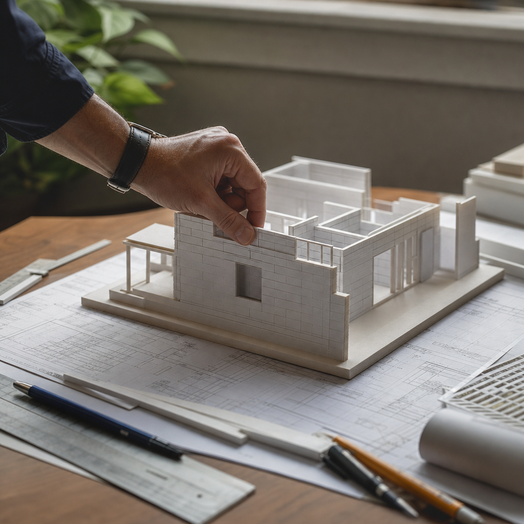
Every structural plan set for new residential construction or major additions in Orlando, FL must embody high-wind design criteria, concrete masonry material standards, and explicit reinforcement details for CMU bond beams. The City of Orlando’s code officials closely review plan sets for compliance with the adopted Florida Building Code (FBC), 8th Edition (2023)-itself based on the 2021 IRC/IBC with state and local amendments, especially regarding wind-load resistance and masonry special inspections. The organization, completeness, and clarity of documented bond beam and rebar details directly impact both permit-review cycles and jobsite constructability.
Orlando’s Adopted Codes, Wind Criteria & General Sheet Notes for CMU Wall and Bond Beam Detailing
Orlando’s Adopted Structural Code Edition and Local Amendments
Permitting requirements for masonry wall construction in Orlando flow from the Florida Building Code, 8th Edition (2023), adopted by Orlando Code of Ordinances, Chapter 13. This edition references ACI 530/530.1 for masonry standards and uses wind speed maps and criteria directly from ASCE 7-16, tabulated in FBC Section 1609 and localized in Section 13.3 of the city ordinances.
- Risk Category I: Ultimate wind speed = 125 mph
- Risk Category II: Ultimate wind speed = 135 mph
- Risk Category III & IV: Ultimate wind speed = 145 mph
The FBC requires permit plans to state project risk category, ultimate wind design speed, and exposure, per FBC Section 1609.4. In Orlando’s residential neighborhoods (R-1, R-2 zoning), Exposure Category B or C dominates-defined by surrounding terrain, influencing the lateral load criteria assigned to all CMU wall and bond beam details.
General Notes for CMU Walls and Bond Beams
Typical plan review in Orlando expects structural general notes to cover:
- Design wind speed, exposure, and risk category
- Material specs:
- CMU to ASTM C90-loadbearing units min. 2,000 psi compressive strength
- Mortar to ASTM C270, usually Type S for structural work
- Grout to ASTM C476, min. 2,000 psi, with explicit mixing and placement notes
- Reinforcing steel to ASTM A615, Grade 60 standard; specify size, spacing, and lap requirements
- Minimum special inspection statement: “Special Inspection of masonry construction per FBC Sections 107.3.5 and 1705.3 is required. All field reports to be submitted to Building Department prior to final inspection.”
- Construction tolerances: Stipulate allowable variation per ACI 530/530.1, e.g., “Plumb and true within 1/4” in 10 feet and ±3/8” overall.”
Drawings must summarize allowable deviations, special inspection triggers, and submittal requirements for field reports in accordance with FBC 107.3.5 and 1705.3, directly tied to CMU wall structural performance.
Wind Design Criteria Documentation and Plan Sheet Call-Outs
Full wind load calculations-factoring Exposure Category, building geometry, and risk category-are mandated for commercial and residential permit sets supporting engineered (reinforced masonry) wall designs. Sheet S-1 typically carries a boxed “Wind Design Criteria” note with:
- “Ultimate Design Wind Speed: 135 mph (ASCE 7-16, Figure 1609B)”
- “Risk Category II Building (Residential, Orlando, FL)”
- Exposure: “C” (if adjacent to undeveloped land or wide water bodies)
Redlines commonly arise when these headlines or wind-load diagrams are missing or incomplete.
Special Inspection Statements and Submission Procedures
Orlando’s permitting workflow requires special inspection declarations for masonry, referenced on drawings per FBC 107.3.5: “Masonry special inspections per FBC 1705.3, for material verification, reinforcement placement, and grouting, are required. Inspection reports to be uploaded prior to requesting framing or final structural inspection.”
Failure to include this statement leads to delays at plan review (“Redline: Provide special inspection statement for masonry per FBC 1705.3.”). Sheet S-1, the cover sheet or structural general notes, is the typical location for this mandatory clause.
Granular Detailing of CMU Bond Beam and Vertical Reinforcement for High-Wind Compliance
Standard Bond Beam Reinforcement-Drawing Conventions and Schedule Illustration
Orlando engineers and reviewers expect bond beams to be fully grouted, utilizing U-shaped open-end blocks, with:
- Horizontal rebar:
- 2-#5 (5/8”) or 2-#6 (3/4”) bars continuous in each bond beam (final size per structural engineer)
- #3 stirrups at 24” O.C. (or denser at high shear/unusual uplift regions-specify per design)
- Lap splice lengths:
- #5 bar: 30” minimum lap per ACI 318/FBC-R Table R608.5.4.5
- #6 bar: 36” minimum lap
- Concrete cover: 1.5” clear to face shell for #5 and smaller, 2” for #6 and up, or 3” where exposed to earth (FBC Section 1907.7.1, ACI 318-25.6)
Drawings should call out “Bond Beam (BB1): 2-#5 cont. w/ #3 stirrups @ 24” O.C., all open-end units, grout solid, 1.5” min. cover. Lap bars 30” min. at butt joints. See Detail 2/S-5.1.”
Vertical Reinforcement-Dimensioning, Grouting, and Schedule Standards
- Vertical rebar:
- #5 @ 48” O.C. typical or #6 @ 32” O.C.-spacing tightens in wind zones, near corners, and either side of openings
- Embedment: Extend vertical bars 12” minimum into footings (or full development as calculated), tied to foundation dowels-see Detail 4/S-6.2.
- Cell grouting: All cells with vertical steel fully grouted; often all cells grouted at end walls and for walls >8’ in height or requiring enhanced wind resistance
- Hooks/Ties: Vertical bars hooked or mechanically tied to horizontal bond beam steel at terminations and at top-of-wall (see enlarged section at S-7.4).
Plan views should mark rebar with circles and tags referencing “V1: #5 vert. @ 48” O.C. (typ.), full grout, lap 30” min. w/ dowels. See Section A/S-6.5.” All vertical/horizontal intersection details demand break-out sections (e.g., S-8, S-9) to clarify laps, bends, and hooks-reducing RFIs for trades.
Construction Drawing Section Details and Elevations
Sheet S-5 should carry typical wall sections-call-outs such as “8”x8”x16” CMU, bond beam at top course, 2-#5 cont., all cells with vertical steel grouted full, see Bond Beam Schedule BB1.” Section cuts “B/S-5.2” illustrate rebar placement within bond beam blocks, cover to face shell, stirrup installation, and vertical steel interface. Provide elevation keynotes indicating bond beam runs at top-of-wall, above doors/windows, and at intermediate levels per uplift/shear zone.
Critical Connection Detailing for Load Path Continuity in High-Wind CMU Construction
Wall-to-Wall Intersections and Corners
Continuous load paths are the spine of high-wind design. Detailing for Orlando plan review should provide enlarged corners and intersection details:
- L-keys/T-intersections: Vertical #5 bars at all intersections grouted full. Call-out “All wall intersections: provide (1) #5 vertical bar, lap 24” min. at intersection, full grout. See Detail C/S-7.2.”
- Horizontal wrap: Bond beam rebar to be bent (without excessive sharpness-see ACI min radius) around corners with a 24” lap. “Corner bond beam: 2-#5 bars, full height bends, 24” lap, see Detail D/S-7.4.”
At plan review, “Clarify rebar continuity at T/corner intersections” is commonly redlined where these details are missing or ambiguous.
Roof-to-Bond Beam Anchorage for Uplift Resistance
Unyielding roof-to-wall connection is essential for compliance with FBC R802.11 and ASCE 7-16 uplift requirements. Plan sheets should show:
- Hurricane ties: Specified by manufacturer and model (e.g., Simpson Strong-Tie H10A rated 795-1,065 lbs. uplift, or H2.5A for 635 lbs.), noted in schedule: “Strap: (1) H10A @ each rafter/truss, embed leg into grouted bond beam, 8-10d x 1-1/2” nails per strap, per mfr, see Detail E/S-8.1.”
- Embedment: Minimum 3” into solid-grouted beam, with strap located within 2” of rebar; strap schedule on S-0.5 (“Strap Sched. - H10A @ all end/truss reactions unless noted”).
- Uplift calculations: Attach tables # per FBC Table R802.11 showing required connection capacity per zone; “Zone 3: H10A at 24” O.C. required per wind calc. summary.”
At review/jobbsite, missing or unclear anchorage type, spacing, or embedment is called out (“Redline: Show strap embedment/fastening per FBC Table”). Explicit annotation avoids confusion and field RFI.
Bond Beam-to-Foundation Ties
- Dowels: “#5 dowels @ 16” O.C., extend into beam 24” min.; lap 24” with vertical wall bars; see Detail F/S-6.2.”
- Footing depth: “Footings min. 12” deep (FBC R403.1.1); see S-2 Foundation Plan.”
- Embedment: “All vertical steel embedded min. 7” in footing, see Section B/S-6.8.”
Plan sheets should match dowel tags in elevation/section (“D1: #5 vert. dowel @ 16” O.C. FDN to BB, typ.”) with keyed bond beam and wall schedules. A disconnected load path is frequently found on initial plan reviews (“Clarify vertical rebar continuity into footing”).
Comprehensive Sheet Layouts, Bond Beam Schedules, and Annotation Protocol for Orlando Submission
Sheet Organization and Detailing Mechanics
The City of Orlando expects structural sheets (S-1 and up) to follow a logical standard:
- S-1: General notes, wind design box, code summary, special inspections declaration
- S-2: Foundation plan - showing grid, footing call-outs, dowels, and marked intersection with wall above
- S-3, S-4: CMU wall layout, all opening dimensions, bond beam runs and tags
- S-5, S-6: Typical wall sections, bond beam and lintel enlarged sections
- S-7, S-8: Connection details-corners, T-intersections, roof anchorage, embedment, vertical/horizontal reinforcement splices
- S-0.5 (or legend block): Bond beam and rebar schedules, symbol legend, abbreviation glossary
Each bond beam run is tagged (“BB1,” “BB2,” etc.) in plan, referencing its detailed entry in the bond beam schedule.
Bond Beam Schedule Example and Cross-Referencing
| Bond Beam Type | Rebar | Grout | Block Type | Notes |
|---|---|---|---|---|
| BB1 | 2-#5 cont. + #3 stirrups @ 24" O.C. | G1 - ASTM C476, 2,000 psi, fine | 8"x8"x16" U-block | Top-of-wall. Lap splices 30" min. All cells grouted full at corners. See Detail D/S-7.4. |
| BB2 | 2-#6 cont. + #3 stirrups @ 12" O.C. | G2 - ASTM C476, 3,000 psi, coarse | 8"x8"x16" U-block | High-shear region above garage door. Provide cleanouts at ends. See E/S-8.1. |
Each tag in plan and section (“BB2 @ Grid Line A”) refers to a bond beam schedule legend and the relevant enlarged detail. Plan review comments in Orlando routinely cite “Missing bond beam schedule” or “Show call-outs for all bond beam runs” when tables or cross-references are lacking.
Dimensioning, Symbols, and Detail Conventions
Standard practice on Orlando plans includes:
- Dimensioning: All wall and bond beam locations dimensioned from face-of-CMU or reference grid (never assume “by scale” in review)
- Symbol legend: “O = #5 vertical bar,” box with “BB = Bond Beam,” etc.
- Abbreviations: O.C. (on center), TYP. (typical), “CONT.” (continuous), “GR. FTG.” (grade footing), “TOC” (top of CMU), etc.
- Detail tags: Always “See Detail X/S-Y.Z” for any intersection, unusual condition, embedment, or non-typical schedule item
The City of Orlando Building Department favors sheets with organized drawing numbers, schedule tables, and a robust “Legend & Notes” box on sheet S-0.5 or S-1. Lost or nonstandard abbreviations are frequent redline items (“Provide legend for symbols/abbreviations used”).
Eliminating Permit Review Redlines and Jobsite Call-Outs for CMU Bond Beams
Common Orlando Plan Review Comments and Proactive Drawing Solutions
- “Clarify vertical rebar continuity into footing.”
Detail wall section with hooked #5 verticals, call-out: “Extend #5 vertical rebar min. 7” into footing, lap 30” with dowel, typ. at all locations. See Section B/S-6.5.” Add general note referencing FBC R403.1.6 min. embedment and include in steel schedule. - “Provide specific lap splice length based on rebar size/grade.”
In rebar schedule: “All #5 bars: lap 30” min., #6 bars: lap 36” min. per ACI 318-25.6.2, FBC R608.5.4.5.” Cross-reference on all plan call-outs with lap requirements; note at each location with “(Lap 30” min.)” in bold. - “Verify bond beam grout compressive strength and placement notes.”
In bond beam schedule and general notes: “Bond beam grout: ASTM C476, 2,000 psi min. Place in lifts not more than 4', consolidate per ACI 530.1.” Add instruction: “Require cleanouts if more than 5' lift is poured, per FBC R608.6, S-6.8.” - “Show strap embedment/fastening per FBC table.”
On roof-to-wall section: “H10A strap, embed in bond beam 3” min., 8-10d nails each leg, per mfr. spec. & FBC Table R802.11.1. See Detail E/S-8.1 and Strap Schedule S-0.5.” Add legend block with model/fastener type and load rating.
Typical Jobsite RFI Scenarios and Drawing Clarification Tactics
- Rebar placement at intersections unclear: Respond with enlarged detail, “T-intersection: (1) #5 vert. bar lapped 24” w/ adjacent wall, tied at mid-height, grout full, Section G/S-8.3.” Issue clarification sketch with explicit bar positions and lap dimensions.
- Grout specification unclear/inconsistent: Fast field response: “All bond beam and vertical bar cells: grout to ASTM C476, fine grout, 2,000 psi min., placed in lifts ≤4’, S-6.2 for cleanout locations.” Add field order instructing grout mix ticket submission to inspector.
- Unclear block type at bond beam: Clarify in both material schedule and enlarged section: “Bond beam block-8”x8”x16” open-bottom U-block, ASTM C90, S-7.1,” with isometric sketch in detail file.
Referencing the permit-approved detail number and noting all manufacturer-specific product data on shop drawings ensures compliance and speeds up plan review re-approvals. Engage structural engineers for dispatch clarifications if field concerns deviate from plans; document all clarifications in ASI/field bulletin log per FBC Section 107.4.
Drawing Quality Assurance-Minimizing Field Errors and Review Delays
- Run all sheet sets through an internal “Orlando redline checklist”-verify embedment, lap, cover, block/grout type, and scheduled detail for every bond beam and wall connection.
- Use digital hyperlinks in PDF sets for “See Detail X/S-Y.Z” call-outs to expedite electronic review and field viewing.
- Provide on-sheet documentation for out-of-sequence pour strategies if construction staging is likely. Supply “Bond Beam Pour Sequence” diagrams as necessary.
Consistent clarity-embedment, lap, mix, cross-references, and code citation on each relevant drawing-almost always precludes repeated “circle back” review rounds and field confusion.
Conclusion-The Benchmark for Code-Compliant CMU Bond Beam Drawings in Orlando
Drafting high-wind-compliant CMU bond beams and connections for Orlando permit plans requires exhaustive code citation, systematic drawing segmentation, meticulous schedule detail, and organization designed for both plan reviewers and field crews. Every dimension, bar size, lap, cover, mix, and fastener schedule must be keyed to FBC, ACI, and ASTM standards, reinforced by explicit notes, schedules, and cross-referenced enlarged details. Anticipating typical review redlines and jobsite call-outs-and embedding their answers into every plan set-anchors both compliance and constructability, reducing delays and RFIs on Orlando’s increasingly scrutinized residential projects.
Kingsway Drafting & Design delivers code-driven, detail-rich permit drawings for Orlando and throughout the U.S. high-wind corridor.