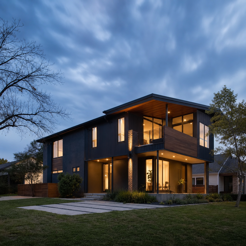
In Dallas, TX, the R-7.5(A) Single Family Residential zoning district-established by Chapter 51A of the Dallas Development Code-regulates minimum lot sizes, setbacks, maximum building heights, and lot coverage. Precision in dimensioning, annotation, and integration of the 2021 IRC/IBC local amendments is not only critical for compliance; it is essential for approving permit sets and avoiding redlines during the plan review process and inspections. The nuances of setback measurement, height determination from the average grade plane, documentation of lot coverage, and workflow navigation through ProjectDox all appear as hard requirements on plan sheets, in notes, and within response letters to city plan reviewers. Grounding every design and annotation decision in the local code text, and referencing the relevant Dallas amendments, keeps projects on track and approvals achievable.
Precision Dimensioning and Annotation for Dallas R-7.5 Setbacks: DDC 51A-4.204(a) Compliance and Common Plan Review Redlines
Setback Mandates as Plan-Sheet Dimensions
DDC Section 51A-4.204(a) stipulates the principal yard setbacks for the R-7.5(A) zoning district:
- Front Yard: minimum 25 feet from the property line
- Side Yard: minimum 5 feet from each side property line for single-family structures; 10 feet for other permitted structures
- Rear Yard: minimum 5 feet from the rear property line for single-family structures; 15 feet for other permitted structures
These requirements are enforced without ambiguity in plan review and must be shown as explicit dimension lines, measured perpendicular from the legal property boundary to the nearest face of the proposed building wall or above-grade structure. Annotated setback lines should be drawn as heavy dashed lines on site and floor plans, with setback dimensions called out at several key points. Labels such as REQUIRED 25’ FRONT SETBACK-PER DDC 51A-4.204(a) clarify compliance.
Projections: Quantifying Allowable Encroachments and Drawing Details
Projections into required yards are often missed or misdrawn, which is a leading cause of Dallas permit redlines. DDC Sections 51A-4.401, 51A-4.402, and 51A-4.403 tightly delineate what is permitted:
- Ordinary projections (window sills, belt courses, pilasters): max 12" into any required yard
- Fireplace chimneys: may project up to 2' into yard, but projection area must not exceed 12 sq ft
- Cantilevered roof eaves/balconies (front yard): allowed up to 5' projection
- Roof eaves (side/rear yards): max 3' projection; balconies not permitted
Detailed section call-outs must illustrate how these projections relate to the setback lines. Plans should include detail bubbles (e.g., See Detail 5/A3.2) at each projection, with a corresponding section cutting through the wall/eave/chimney, the property line, and the exact setback line, all labeled. Annotations such as ROOF EAVE PROJECTS 2’-10” INTO 5’ SIDE YARD, COMPLIES W/ DDC 51A-4.401(b)(2) are expected by reviewers.
Common Redlines and How to Prevent Them
City of Dallas plan reviewers frequently return redlines for:
- Setback encroachments: misplacing building elements within the required setback, particularly with overhanging portions (porches, bay windows)
- Projection overages: chimneys or eaves extending further into yards than permitted, or illegal balcony projections
- Ambiguity: setbacks and property lines not dimensioned from correct surfaces or not dimensioned at all
Preventing these resubmissions requires:
- Every setback dimension labeled from the boundary to the closest edge of building/structure, not to finished cladding or overhang; e.g., to foundation face if relevant
- Projection details with measurements and code references
- Clear, cross-referenced plan notes invoking DDC section numbers-the reviewer should not wonder about code intent
Code-excerpted referentials (All projections per DDC 51A-4.401(b)) reinforce compliance within the drawing set.
Dallas R-7.5 Building Height Calculations: DDC 51A-4.204(a)(7) Measurement from Average Grade Plane on Elevations and Sections
Calculation Methodology: Grade Plane as Datum
According to DDC 51A-4.204(a)(7), “building height” is measured from the average grade plane to the highest point of the structure. “Grade” is defined in Dallas as the average finished ground elevation at the highest and lowest exterior corners of the building. This local standard aligns with the IRC and IBC Section 202 “grade plane” definitions, but always apply the Dallas code reference in B1 notes and height calculations.
Every elevation sheet, and at least one building cross-section, must graphically represent:
- Two call-out points: “Highest finish grade at [corner A], Elev. 472.1’” and “Lowest finish grade at [corner B], Elev. 464.3’” sampled at building corners
- The average grade plane: AVG GRADE = (472.1’ + 464.3’) / 2 = 468.2’
- Measurement arrows: Average grade plane to highest roof ridge = 30’-0" max
- Annotation: Height per DDC 51A-4.204(a)(7); see Sheet A2.0 for grade datum calculation
It is never permissible to use average finished floor elevation or midpoint roof heights for code maximum comparisons; plan reviewers will require average grade plane, with dimensional call-outs directly reflecting DDC terminology.
Plan Review Redlines for Height
Typical review comments include:
- “Provide calculation of average grade plane-missing or unclear on elevations”
- “Height exceeds 30’ measured from average grade; revise elevations and resubmit”
- “Show reference points for both highest and lowest grade positions at building corners”
Addressing these requires explicit annotation, checked against the finished site grades shown on the civil site plan. For sloped sites, contour references and spot elevations at corners should also be shown on the grading plan (C series) and cross-referenced in the architectural (A series) sheets.
Dimensional Standards and Code References
- Maximum height: 30 feet (R-7.5(A), per DDC 51A-4.204(a)(7)), measured per above
- All calculations and measurement origins: explicitly labeled and code-referenced
- Annotate any dormers, parapets, chimneys: Note if/where exempted projections allowed (see DDC 51A-4.409 Exemptions)
Mastering R-7.5 Lot Coverage in Dallas: DDC 51A-4.204(a)(4) Impervious Surface Calculation and Site Plan Documentation
Lot Coverage: Building Footprint Calculation and Plan Documentation
The Dallas Development Code Section 51A-4.204(a)(4) sets the maximum allowable lot coverage for residential structures in R-7.5(A) at 45% of the lot area. Lot coverage is defined as the portion of the site covered by the building footprint-including covered porches and accessory buildings-but excluding driveways, walks, pools, and open patios. DDC language (see R-7.5 Overview at dallascityhall.com) does not currently count impervious surfaces such as paving in lot coverage, though this is under review for environmental reasons.
Site plans submitted for permit must include:
- Property lines with heavy lines and plotted dimensions matching survey
- Total lot area in square feet: LOT AREA = 7,878 SF (Example from DCAD/Survey)
- All structures drawn in plan and shaded/hatched; each area computed numerically (e.g., RESIDENCE: 2,300 SF, GARAGE: 420 SF, PORCH: 180 SF…)
- Coverage calculation table: totals for all included elements, divided by total lot area (TOTAL BUILDING FOOTPRINT = 2,900 SF; 2,900/7,878 = 36.8% (Under 45%))
- Annotation: “Lot coverage equals 36.8%. Maximum permitted = 45% per DDC 51A-4.204(a)(4).”
Failure to provide this tabulation, or incorrectly including or excluding elements, generates zoning redlines such as:
- “Coverage calculation missing; resubmit with breakdown of each covered area”
- “Pool deck, concrete walk included in coverage; only building footprint counts”
Impervious Surface Code Amendments and Their Effect
Though not yet codified in 51A, proposed amendments (see Impervious Coverage Code Amendment July 2024) are under consideration to limit impervious coverage by district to address stormwater and heat island effects. If adopted, plan sheets will need a second “Impervious Surface Calculation” table, counting not just structures but also driveways, walks, patios, and hardscape. Drafters should be prepared to annotate both lot coverage and impervious coverage with code references and legend distinctions, using unique hatch patterns for each category.
Site Plan Conventions, Drawing Details, and Material Specifications
- Property boundaries: show all metes and bounds (recorded survey), total area labeled
- Setbacks: graphically dimensioned from boundaries to primary structure-annotate as “5' Side Yard Setback-Per DDC”
- All existing/proposed buildings: footprints accurately drawn; all elements to be included in lot coverage hatched distinctly
- Lot coverage tabulation: on cover sheet or site plan sheet, summarized in designed box, e.g., LOT COVERAGE: 2,900 SF = 36.8% (max allowed 45%)
- Parking/circulation: Include location and number of parking spaces (2 min. for SFD) per DDC. ADA compliance not generally required for one- and two-family dwellings but note if project triggers special case.
- Driveways/hardscape: On separate color or hatch for impervious coverage (if/once adopted by Dallas)
- North arrow, scale, DCAD parcel number: Always required in Dallas electronic submissions
Material specifications, especially in Dallas’s expansive soils, should reference minimum 3,000 psi concrete (for slabs, per industry standard), 12’+ pier embedment if a soil report requires, 10-mil vapor barrier, and rebar call-outs as recommended by geotechnical analysis (Kingsway Drafting).
Integrating Dallas's Adopted 2021 IRC/IBC Amendments and Zoning Overlays into R-7.5 Single-Family Dwelling Plans
Zoning and Code Coordination for Plan Sets
The City of Dallas adopted the 2021 IRC/IBC with amendments in 2023 (Dallas Builders Association). The interplay of these with R-7.5(A) zoning overlays, especially in older neighborhoods or Planned Development Districts (PDs), appears on plans as layered requirements. Minimum lot size (7,500 sf), setbacks (25’/5’/5’), lot coverage (45%), and building height (30’) are shown as core overlay notes on the zoning data block-usually on the cover sheet or site plan. If the property lies within a special zoning overlay, all unique requirements (e.g., architectural control, fence heights, landscape minimums) must be detailed in boxed notes and as overlays on the site plan graphic.
IRC/IBC Amendments: Foundation, Framing, Energy, and Material Documentation
The 2021 IRC (Dallas-amended) is the effective residential code. Key amendments for Dallas conditions include:
- Foundation: IRC R401.2 requires foundations to account for all loads and route them to bearing soil. Dallas demands fill soils supporting any footings must be engineered (with geotech letter, compaction test), and typically requires foundation details to reference both “Per IRC R401.2, Dallas Amends-Fill under Foundation Engineered/Certified”.
- Framing-Wind Uplift/Tie-downs: Dallas requires frame anchorage for wind loading per IRC Chap 6, including uplift connectors (hurricane clips) at all rafter-to-plate conditions.
- Energy: The 2021 IECC (with local amendments) sets insulation/energy metrics. Typical wall insulation is R-13 or better, attic R-38 minimum, and window/door U-factor requirements. Sectional details must show batting, foam or spray insulation, and SHGC (solar heat gain coefficient) for glazing.
- Fire and Life Safety: Where fire separation distance is less than 5 feet, walls and eaves on those sides must be 1-hour fire-rated per IRC R302. Boundary lines and corresponding wall ratings must be called out on the site and floor plans-“3’-0” South Wall-1 HR FR RATED-PER IRC R302.1, DDC 51A-4.402”.
Plan review will cite missing or incorrectly referenced details, especially for fill-compacted sites, pier-and-beam foundations, and residential infill projects with zero-lot-line overlays. Annotate in general notes and at detail callouts with both national code and Dallas amendment reference numbers.
Standard Drawing-Sheet Conventions for Code/Overlay Integration
- Title block: Full project address, DCAD parcel, legal lot/block, zoning district, overlay indication (“PD-808” if applicable), sheet number, drafter’s contact
- Code note box: List primary controlling codes and city amendments-2021 IRC (Dallas Amendments), 2021 IECC, DDC 51A, plus any overlays or PD-specific rules
- Site plan: Overlays with setback lines, lot coverage graphic, and annotation of all district/overlay restrictions
- Elevations/sections: Indicate maximum allowed height (“Max. Height 30’, Measured from Average Grade-DDC 51A-4.204(a)(7)”), finished floor elevations, eave heights
- Foundation details: Show soil report reference, fill/compacted zones, vapor barrier and rebar per local engineering practice
- Schedules: Windows, doors, mechanical equipment-specify energy compliance (U-values, SHGC per 2021 IECC, Dallas)
All code notes and overlays must cite official DDC and Dallas code amendment section numbers. If any overlay or PD rules diverge from standard R-7.5 requirements, flag the exception at relevant detail bubbles and in a boxed note (“Plan Review Note: SFD Height in PD-XXX = 35’ per PD text, controls over R-7.5(A), DDC 51A-4.508(a)”).
Dallas Permit Workflow for R-7.5 Plans: Navigating ProjectDox Submissions and Effectively Responding to Zoning Redlines
Preparing a Compliant Electronic Plan Set
The City of Dallas accepts all permit plan submittals for single-family projects via ProjectDox (ProjectDox Portal), requiring strict digital formatting and data alignment:
- File standards: All sheets PDF’d individually (not as one book), following the city’s sheet numbering system (e.g., A1.1 Site Plan, A2.0 Floor Plan, S1.1 Foundation Plan), and 3”x3” blank corner on each sheet for city stamp
- Sheet organization: Cover/Index, Zoning/Data Summary, Site Plan, Floor/Elevation/Section, Schedules, Details, Energy/Engineering Sheets (if required)
- Standard notes: All city-required code callouts and references, DCAD number on every titleblock
Failure to follow file naming, sheet sequence, or missing key data generates not only permit delays but sometimes outright rejection until resubmittal is completed. Drafters should double-check the city’s current “Plan Review Submission Guide” before every upload.
Responding to Plan Review Zoning Redlines
The principal redline comments for R-7.5(A) submittals originate from improper setback annotation, over-coverage, and incomplete height or floor area calculations. The workflow for addressing these redlines-almost always required to be uploaded with a “Response Letter” document-includes:
- Read each redline within PermitHub or ProjectDox “Corrections” interface; cross-check the cited code or detail for intent
- Revise plans as required: Add or correct dimension lines; update shading or hatched area for coverage; recalculate height per average grade; fix or add code section bubble references
- Prepare a response letter: For each item, cite how the correction was addressed, referencing sheet numbers and detail locations (“Setback violation at north side addressed by shifting building footprint to centerline; dimension now reads 5’-2” per DDC 51A-4.204(a). See A1.2/Detail 3.”)
- Resubmit through ProjectDox; ensure all revised sheets are “versioned” or replaced as per city instructions; verify all files are unlocked and flattened
After corrections, the city will update status in ProjectDox and return either additional comments or approval for issuance after final checks.
Annotation and Drawing Standards in Submittal Sets
Dallas expects, and reviewers enforce, use of standardized drafting conventions and annotation legends, including:
- Consistent title blocks (project name, address, DCAD #, unique sheet number, date and revision history)
- North arrow and graphic scale on every plan or site-based sheet
- Distinctive hatching for building area, impervious area (if required), landscape zones, and reference to each area in the site legend
- Legend for all plan symbols, section/section cut bubbles, elevation tags, and code annotation bubbles
- Revision block clearly marking all post-submittal changes (date, revision number, brief description)
Structural details must show all code-required material specifications and ratings set by Dallas’s adopted 2021 IRC amendments. This includes stud/joist sizing, wall and floor fire ratings, insulation R-values, glazing U-values and safety requirements, and detailed connection type at foundation, wall, and roof.
Dimensional and Specification Detail Required per Code
- Setbacks: minimum front 25', side 5', rear 5', dimensioned explicitly from correct property lines
- Height: max 30' measured from average grade plane per DDC; graphically shown on all elevations
- Lot Coverage: max 45% for R-7.5(A), with separate calculation for building area and, if required, impervious area
- Structural materials: call out minimum compressive strength for concrete (3,000 psi), rebar grade, embedment depths for foundation piers, insulation minimums per 2021 IECC/Dallas, and any required fire ratings per IRC
- Parking: at least two spaces per unit, dimensioned at 9’ x 18’ each (as typical), with driveway location keyed to site plan
The city’s reviewers frequently note missing, ambiguous, or unreferenced dimensions and materials-each must be explicitly tied to a standard or amendment citation on the drawing for full approval.
Conclusion
Dallas’s R-7.5(A) zoning district establishes a code-driven and highly codified review process for single-family residential permit drawings: plan sets must demonstrate all setbacks, lot coverage, and height calculations with precise dimensions and graphic annotation per DDC 51A-4.204, integrating every applicable 2021 IRC/IBC amendment and overlay. The city’s ProjectDox workflow, along with its redline-driven review process, compels rigorous coordination across all sheets; zoning, code, and site requirements are inseparable from drawing and annotation standards. Success in Dallas permit approval is rooted in measured compliance-drawings must not only show what is proposed, but how every element satisfies code down to the inch, the material, and the case-law of redline response. For uncompromising compliance, clarity, and permit approval across Dallas’s stringent standards, Kingsway Drafting & Design sets the gold benchmark in residential architectural documentation.