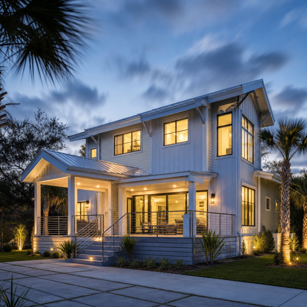
Florida Building Code (FBC) 8th Edition (2023) is fully adopted in Tampa, with local amendments from Hillsborough County, requiring plan sets to justify exterior wall cladding fastening with wind-load calculations, explicit schedules, and references to approved materials for wind speeds of 150-160 mph. Every step from general notes to construction details must concisely transmit compliance with ASCE 7-22, city review standards, and the distinct needs of Tampa’s high-wind, hurricane-prone environment. Cladding details and schedules must reference Florida Product Approvals (FLPA), match exact plan notes to manufacturer’s installation guidelines, and withstand scrutiny during both plan review and jobsite inspections-where QA/QC gaps can trigger costly redlines and delays.
Drafting General Notes and Design Criteria: FBC 8th Edition (2023), Wind Load, and Tampa Amendments
Establishing the Structural Basis of Design
Cladding details begin on the cover (A0.0) and general notes (G-series) with structural wind criteria. For Tampa and Hillsborough County, these must strictly follow FBC-B Section 1609 and FBC-R Section R301.2.1.1 with calculations anchored in ASCE 7-22. The “Structural Design Criteria” section on G-001 typically appears as follows:
- Governing Code: FBC 8th Edition (2023), including local Hillsborough County/City of Tampa amendments
- Wind-Load Design Standard: ASCE 7-22, Chapters 26-30
- Ultimate Design Wind Speed (Vult): 150 mph (Risk Category II); 160 mph (Risk Category III & IV)
- Risk Category: II (Residential); III/IV as required
- Exposure Category: “C” (open terrain/scattered obstructions; default for much of Tampa); "D" for coastal properties with open water exposure
- Component & Cladding Pressures: Calculated per ASCE 7-22 based on location, height, exposure, and effective areas
Plan reviewers flag generic or incomplete criteria; a frequent comment is: “Wind design criteria reference outdated code or fail to state exposure zone-revise for ASCE 7-22 and correct wind speed.” The cover and general notes must explicitly state: “DESIGN FOR 160 MPH ULTIMATE WIND SPEED, EXPOSURE C, COMPONENT & CLADDING PRESSURES PER ASCE 7-22.” Each risk category must be justified for its occupancy use as defined in FBC-B Table 1604.5.
Addressing Local Amendments and Digital Submittals
Hillsborough County (Sec. 8-1.1) mandates that plans be digitally signed and sealed by a Florida-registered design professional and that impact protection be detailed for any structure in a mapped wind-borne debris region (“Vult ≥ 140 mph” per county code). All plan sets must explicitly confirm: “Design includes impact-resistant glazing or protectives consistent with wind-borne debris zone.”
Structural Fastener Requirements and Material Specs
FBC-B 2304.10.1 requires that wood connections follow the fastening schedule, including type, size, and spacing of fasteners (“Nails or screws must meet ASTM F1667 and be corrosion resistant”). For sheathing: “Minimum thickness and nailing patterns per FBC-B Chapter 23.” For glazing: “Impact-resistant or protected by Florida Product Approved systems per map zone.”
Standard Drawing-Sheet References and Notation Strategies
- Cover Sheet (A0.0): “ALL EXTERIOR CLADDING FASTENING PER FBC-B 1609, ASCE 7-22, Vult = 160 MPH, EXPOSURE C, FLPA AS NOTED.”
- General Notes (G-001): Table with columns for code edition, risk category, wind speed, exposure, pressures, and referenced FLPA/NOA numbers; a sample format:
- “Fastening Schedule per FBC-B 2304.10.1 and FBC-R R703, see S-501.”
- “All window/door openings comply with wind-borne debris region requirements.”
Dimensioning and clear note blocks are central: missing a single exposure category call-out is a common plan review redline (“Sheets A0.0 and S-1 do not specify exposure-revise to mark ‘EXPOSURE C’ per survey data.”)
Developing Precise Fastening Schedules and Wind Zone Detailing on Plan Sets
Tabular Fastener Schedules Aligned to Wind Pressure Zones
The plan set must organize the fastening schedule in tabular format-typically on the S-series or A-series detail sheets. A standard table will list, for each cladding type (ex: sand-cement stucco, fiber cement, vinyl siding):
- Field (Zone 1): Fastener @ 16" o.c. into studs or approved substrate
- Edge (Zone 2): Fastener @ 12" o.c.-field marked with a thick dashed border on plans
- Corner (Zone 3): Fastener @ 6" o.c.-zones called out with solid hatching or keyed note “C1/C2” per ASCE 7-22, Figs. 30.3.1-30.4.1
Sample schedule excerpt (for fiber cement board, based on FBC Table R703.3.4 and manufacturer guidance):
- Cladding: James Hardie HardiePlank Lap Siding (FLPA #FL12345-R6)
- Fastener: 0.113" dia. hot-dipped galvanized roofing nail, 2" long, corrosion resistant
- Embedment: Minimum 1.5" into wood framing
- Zone 1 (Field): 16" o.c.
- Zone 2 (Edge): 12" o.c.
- Zone 3 (Corner): 6" o.c.
Schedule must state: “ALL WIND ZONE FASTENING SPACINGS ARE MEASURED PERPENDICULAR TO PANEL EDGE, FASTEN INTO FRAMING; SEE ELEVATION/SECTION DRAWINGS FOR ZONING.”
Graphical Representation: Elevations, Sections, and Plan Sheets
Elevations (A2-series) and wall sections (A4/A5, S-501) overlay wind zone boundaries-using broken lines and circle markers keyed to schedule notes. Edge/corner conditions are called out “6” o.c. FIBER CEMENT FASTENER-ZONE 3” with leader lines; field areas with “16” o.c. FASTENER-ZONE 1.” At corners, call out: “PROVIDE 6” o.c. FASTENERS FULL HEIGHT, SEE S-501/3.”
Details for openings and terminations must include specific note blocks: “FASTENERS TO BE LOCATED WITHIN 1.5” OF WINDOW/DOOR JAMBS, AT HEAD/SILL AS PER DETAIL 5/A4.2.”
Dimensioning and Embedment Controls
- Fastener Diameter: Not less than 0.113”
- Minimum Embedment: 1.5” into studs/struct framing-dimensioned on section details
- Spacing Tolerance: +/- 1/4”-noted in QA/QC block
- Fastener Type Annotation: “HD GALV. ROOFING NAILS-SEE DETAIL S-501/5”
Plan reviewers frequently redline inconsistent spacing or fastener types: “Section A4.1 does not match fastening schedule for corner zones-reconcile with schedule and revise call-outs.”
Water and Impact Resistance Requirements
All wall claddings must prevent water intrusion (FBC-B 1403.2) and, in wind-borne debris regions, exterior glazing must be impact-resistant or protected (“All cladding/flashing at openings to meet FBC wind-borne debris region requirements; detail on A4.3/7.”)
Plan notes should read: “EXTERIOR SHEATHING AND FASTENERS TO PROVIDE CONTINUOUS SECONDARY WATER BARRIER PER ASTM E331.”
Integrating Florida Product Approvals (FLPA/NOA) and Manufacturer’s Installation in Drawings
Referencing Approved Cladding Systems on Drawing Sheets
City of Tampa requires explicit product approval call-outs (see tampa.gov): “ALL SIDING TO COMPLY WITH FLPA #FLXXXXX-Rn AS INDICATED.” Each system listed in plan schedules or detail leader notes must include the current approval or revision number, e.g., “James Hardie HardiePanel, FLPA #FL12067-R8.”
- Title Block Reference: “PROJECT CLADDING: SEE FLPA #FL12345-R6, NOA #18-0511.08.”
- Detail Sheet Call-out: “FIBER CEMENT SIDING: INSTALL PER FLPA #FL12345-R6; FASTENING AS PER TABLE S-501.1.”
Lack of an FLPA/NOA reference is a guaranteed redline: “Sheet A4.2: Specify FLPA or NOA # for all cladding-attach documents with permit package.”
Manufacturer’s Installation Instructions and Fastener Specification Notes
FBC-R703.3.3 and FBC-R703.3.4 demand installation “strictly in accordance with the manufacturer’s approved instructions and Florida Product Approval.” General notes must say: “INSTALL XYZ SIDING SYSTEM PER FLPA #FLXXXXX-R2, USING FASTENERS, SEALANTS, AND ACCESSORIES AS SPECIFIED.” Keyed references guide contractors to full installation instructions submitted in the permit docs.
Fastener schedule should cite both code and manufacturer, e.g.: “FASTENER: 0.113” GHD NAIL (MIN 1.5” EMBEDMENT) PER FLPA #FL12345-R6 AND HARDIE INSTALL BUL. JHA 0096.”
Dimensioned Schedules and Edge/Critical Zone Instructions
- At Field (Zone 1): “16” O.C. INTO STUDS, 0.113” HD GALV. NAIL, 1.5” EMBED”-DRAWN AS SECTION ON S-501/2
- At Corners/Edges (Zones 2/3): “6” O.C. AT 6” FROM EDGES AND EXTERNAL CORNERS-SEE PLAN ZONING DIAGRAM”
For any siding installed over foam or non-structural sheathing, a note must indicate: “ALL FASTENERS TO PENETRATE THROUGH SHEATHING INTO STRUCTURAL FRAMING MIN 1.5”-CONFIRM PER FLPA/NOA.”
Addressing Product Data & Drawing Discrepancies
Discrepancies between product approval and plan detail prompt plan review comments such as, “A4.1 fastener spec does not match FLPA #FL12345-revise for consistency with manufacturer/FLPA schedule.” Best practice is to insert a matrix comparing drawing fastener types and spacings versus FLPA figures, or to include scanned pages from product approvals in the permit set appendix.
Addressing Common Plan Review Redlines from Tampa Building Department
Frequent Redline Comments and Their Code Basis
- Inadequate Fastener Schedules: “Fastener schedule provided does not comply with FBC requirements; specify correct type and spacing.”
- Missing or Incomplete Wind Load Calculations: “Provide wind load calculations per FBC Section 1609 and ASCE 7-22 for cladding system.”
- Poor Detailing at Openings and Corners: “Cladding details at window and door openings are insufficient; provide flashing and fastener sections.”
- Lack of FLPA/NOA Documentation: “Submit FLPA or NOA documentation for proposed cladding materials.”
- Drawings Do Not Match Product Approvals: “Cladding section details do not match installation criteria in NOA-revise for compliance.”
Code and Plan Sheet Best Practices
Drawings must include:
- Explicit Fastening: “SIDING FASTENERS: HD GALV NAILS, 2”, 0.113” DIA, 16” O.C. FIELD, 12” O.C. EDGE, 6” O.C. CORNER”-PER FLPA #FLXXXXX-R4.”
- QA Block (S-502 or G-002): “VERIFIED AGAINST FLORIDA PRODUCT APPROVAL NO. FLXXXXX, WITH CORRELATING INSTALLATION DETAILS AS SHOWN.”
- Flashing and Water Detailing: “CONTINUOUS FLASHING AT ALL HEADS, SILLS, AND CORNERS PER DETAIL S-501/4.”
- Opening Details: “PROVIDE FASTENERS WITHIN 1.5” OF OPENING PERIMETER; ALL PENETRATIONS TO BE SEALED, SEE A4.4/2.”
- Impact Region Call-Out: “ALL OPENINGS TO COMPLY WITH FBC WIND-BORNE DEBRIS REGION, SHOWN SHADED ON SITE PLAN.”
Revision and Resubmission Strategies
- Redline Review: Carefully list every plan comment, referencing code section or FLPA where missing criteria was cited.
- Engineer/Architect Coordination: Ensure all wind load calcs, pressure tables, and zone diagrams are sealed/dated and match sheet call-outs.
- Sheet-by-Sheet Correction: Revise all discrepancies-don’t change only one view. For instance, revise both A4.1 and S-501/5 if schedule is updated.
- Document Inclusion: Attach current FLPA/NOA sheets in permit set; index approval numbers in sheet G-002 or A0.0.
- QA/QC Re-Check: Run a “cladding schedule/bubble check”-highlight all areas on the plan set where cladding fastener notes MUST match FLPA/NOA-before resubmitting.
Case Study: Typical Revision Cycle Excerpt
Redline: “A4.2 cladding fastener pattern does not match NOA 20-0324.05 spacing; clarify in schedule and matching detail.”
Corrective Actions:
- S-501 table revised: “Zone 3: Fasteners 6” o.c. both directions, 1.5” min. embedment per NOA 20-0324.05”
- A4.2 detail leader amended to: “ATTACH HARDIEPANEL PER TABLE S-501.1, FLPA #FLXXXXX-R2.”
- General Notes (G-001) now reads: “ALL CLADDING DETAILS AND INSTALL TO CONFORM TO FLPA/NOA AS INDEXED BELOW.”
Jobsite-Ready Fastening Details and QA/QC Call-Outs for High-Wind Zone Cladding
Dimensioned Details for Critical Interfaces
Construction detail sheets (S-501, A4.1-A4.6) must include granular, notated, and dimensioned sections at:
- Window/Door Perimeters:
- “FASTENER WITHIN 1.5” OF JAMB; 6” O.C. HEAD/SILL; 0.113” GALV NAIL; VERIFY 1.5” MIN. EMBED.”
- Leader: “SEE S-501/5 FOR TYPL. FASTENING PATTERN.”
- Soffit Transitions:
- “FASTEN CORNER POST THROUGH ALL LAYERS, MIN. PENETRATION 1.25” INTO BLOCKING; 12” O.C. TYP.”
- Section note: “ACCORDING TO FBC TABLE 1404.15.2; NOA #19-0701.10.”
- Outside Corners:
- Detail call-out: “STRUCT FASTENERS @ 6” O.C. VERTICALLY; STAGGER IF MULTI-PLY.”
- Control/Movement Joints:
- Note: “CONTROL JOINT TO INCLUDE FLEX SEALANT AND HD FASTENERS @ 12” O.C. EACH SIDE; SEE A4.5/3.”
Dimension lines indicate exact distances (e.g., 6", 12", 16" o.c.) and embedment depth, with the call-out: “ALL FASTENERS FIELD-VERIFIED; SEE QA BLOCK.”
Soffit details must note: “SOFFIT PANELS TO BE SECURED WITH 1½” GALV. FINISH NAILS @ 12” O.C. AT BLOCKING; PROVIDE L-METAL TRIM AS SHOWN.”
QA/QC Jobsite Call-Outs and Submittals
- Sheet QA/QC Block (e.g., S-502):
- “ALL EXTERIOR WALL FASTENERS TO BE VERIFIED FOR MINIMUM EMBEDMENT AND SPACING PRIOR TO INSPECTION.”
- “INSTALLER SHALL PROVIDE AFFIDAVIT OF CLADDING COMPLIANCE WITH FBC AND FLPA/NOA #s AS INDEXED.”
- “INSPECTOR TO VERIFY FASTENER CORROSION RESISTANCE AND SPACING AT ALL ZONES (REF SCHEDULE).”
- Install Notes:
- “ALL FIELD PENETRATIONS AT OPENINGS TO BE FLASHED AND SEALED, SEE DETAIL S-501/6.”
- “CLADDING SYSTEMS TO MAINTAIN WATER-RESISTIVE BARRIER (ASTM E331) AND PROVIDE CONTINUOUS DRAINAGE PLANE.”
QA blocks routinely trigger field observation during inspection. Tampa building officials often require: “INSTALLER AFFIDAVIT OR PHOTO DOCUMENTATION OF FASTENER EMBEDMENT PRIOR TO FINAL INSPECTION.”
Material and Fastener Specifications On Drawings
- Fasteners: 0.113" dia. hot-dipped galvanized nail, 2” min. length, 1.5” embedment (per FBC/B 1404.15.1.1, ASTM F1667)
- Cladding: Vinyl siding-ASTM D3679; Insulated vinyl siding-ASTM D7793; Fiber cement-HardiePlank FLPA #FL12345-R6
- Pressure Design: Must match FBC Table 1404.15.2 for mapped wind speed/exposure
Sample Complete Detail Note
“FIELD FASTENERS: ALL FASTENERS TO BE HOT-DIPPED GALVANIZED ROOFING NAILS, 0.113” DIA, 2” LONG, 1.5” PENETRATION INTO FRAMING, SPACED AS SCHEDULED AND SHOWN. AT CORNERS AND OPENINGS, SPACE FASTENERS 6” O.C. WITHIN 1.5” OF EDGE. VERIFY PRIOR TO INSPECTION. INSTALLER TO SUBMIT SIGNED AFFIDAVIT PER FLPA #FL12345-R6.”
Tying It All Together for Permit, Field, and Inspection
Every sheet must cross-reference the QA/QC block, FLPA/NOA, and code notes. G-001: “ALL WORK TO BE INSPECTED FOR FIELD COMPLIANCE WITH FASTENING SCHEDULES, FASTENER TYPE, SPACING, AND EMBEDMENT. COMPONENT AND CLADDING PRESSURES PER ASCE 7-22.” This ensures a closed loop from code compliance at plan review to jobsite inspection and final sign-off.
Conclusion
Cladding fastening schedules for Tampa’s high-wind zones demand direct translation of FBC 8th Edition (2023), ASCE 7-22 wind loads, and FLPA/NOA specifications onto drawing sheets-with each schedule, detail, and note written for both plan reviewer and jobsite installer. Schedules and details are mapped zone-by-zone and benchmarked against actual product installation sheets, verified before and during inspection, and closed out with installer affidavits and city sign-off. Omission of a single call-out, or misalignment of fastener specs, triggers redlines and delays. Attention to every detail-code citation, manufacturer reference, spacing, and embedment-secures both project approval and the long-term resilience of the building envelope in Tampa’s challenging conditions.
Detailed, code-synchronized documentation is at the heart of Kingsway Drafting & Design’s approach for high-wind zone building success.